The Espresso Machine Restoration site
A non-commercial site for those interested in espresso equipment repair and restoration.

Magnetic contactor switches (MCS) and Solid State Relays (SSR) allow a small device to be able to control a much
larger device. Or in other words we use a very small current to control a much larger current safely. The most
glaring example is the CEME pressure switch. Here we have a component that is rated to around 10Amps
controlling heating elements that draw as much as 30Amps. So how is this possible?
This is possible because in actual fact the CEME p-stat is not controlling the heating elements but is controlling a
MCS. The MCS is then controlling (and handling the power) of the heating elements. Think of the MCS or SSR as a
middleman.
So the flow would be:
P-stat switches the MCS on/off. The MCS switches the elements on/off.
If we just connected the p-stat directly to the heating elements then the switch would burn out in no time at all and
would be rather dangerous.
If you want a basic overview of relays and solid state devices I suggest you have a look here.
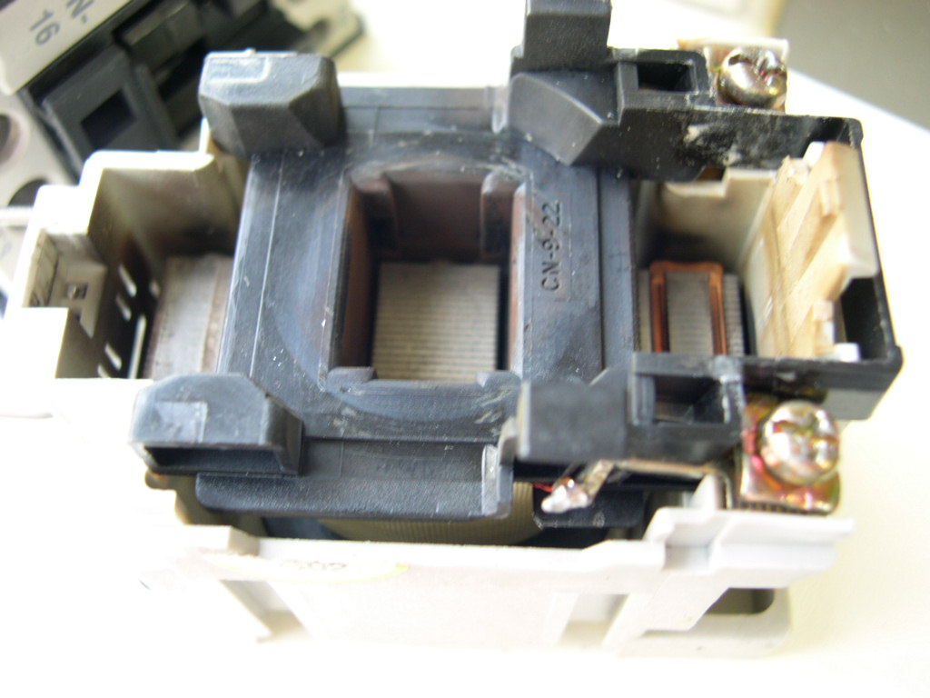
As stated above, the point of relays is that a small current can control a much larger current. The smaller current
which is for example supplied by the p-stat energises a coil, this closes the contacts in the switch. So therefore the
p-stat is controlling the switching of this coil rather than the heating elements.
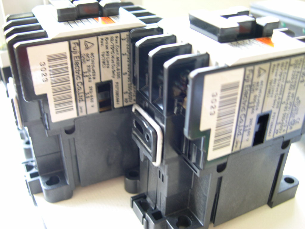
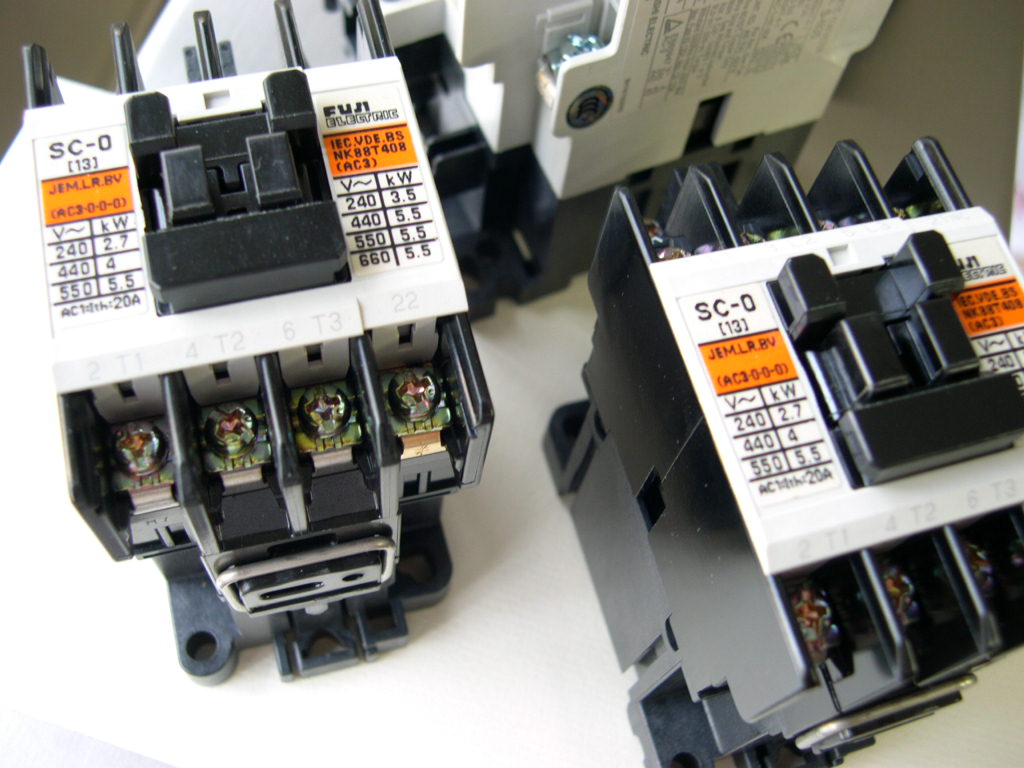
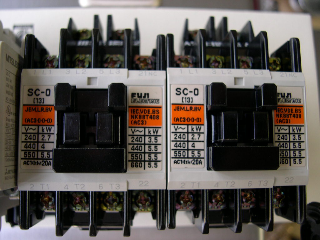
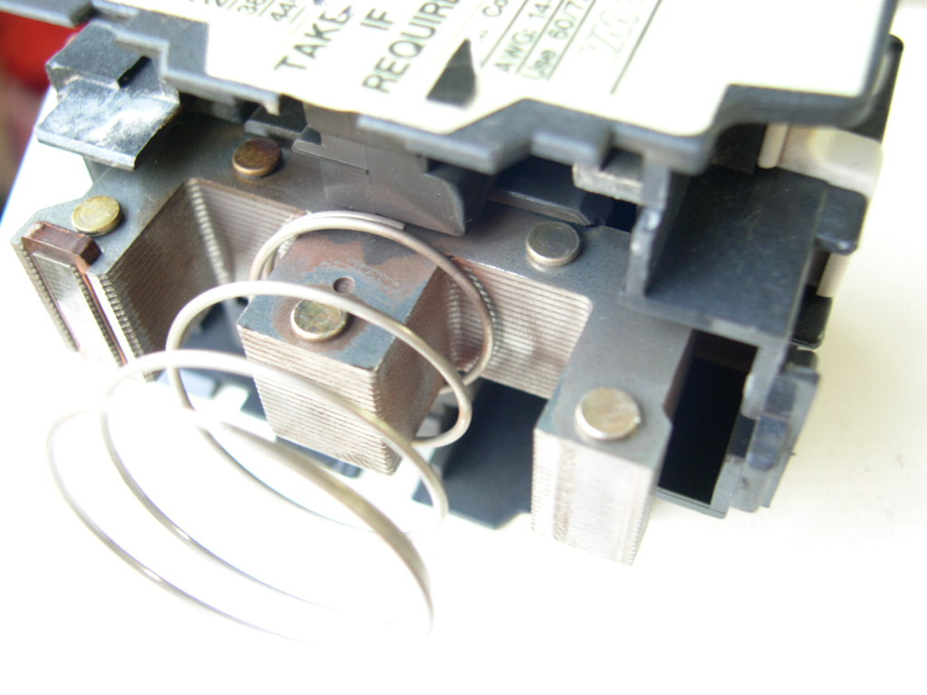
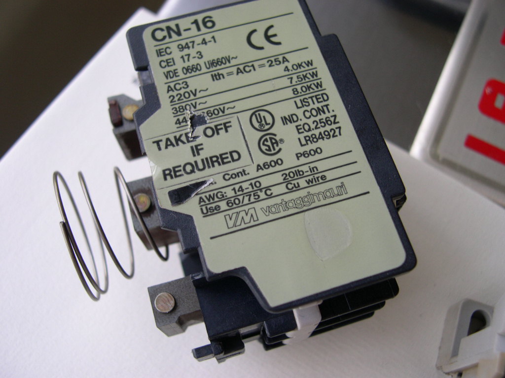
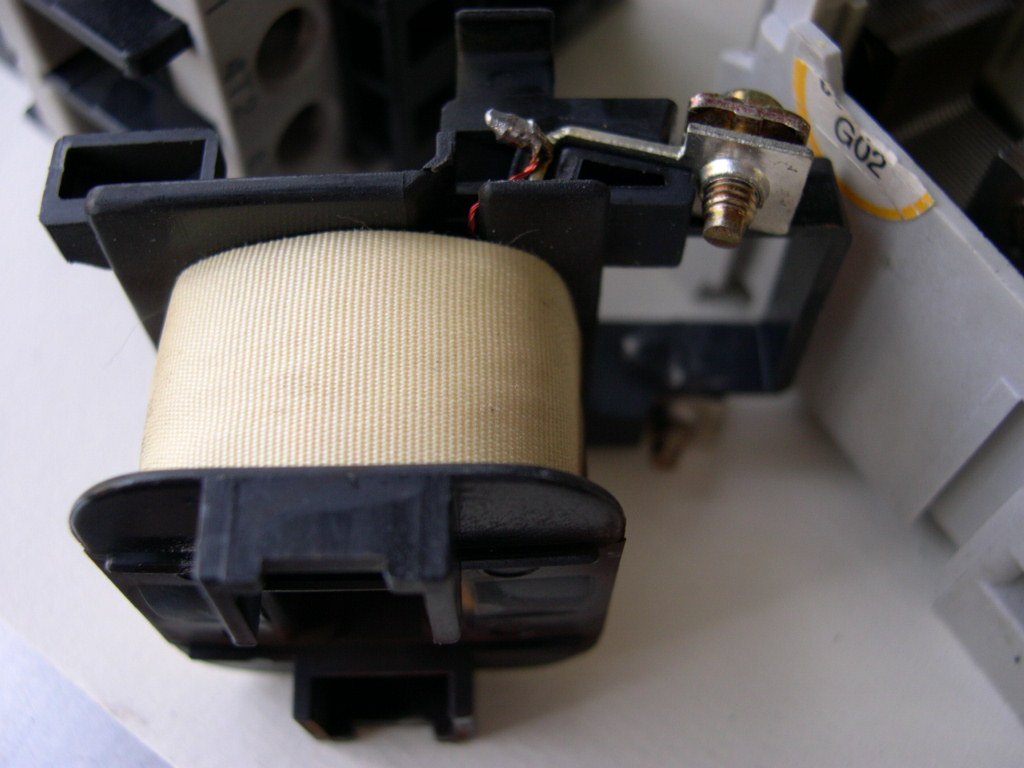
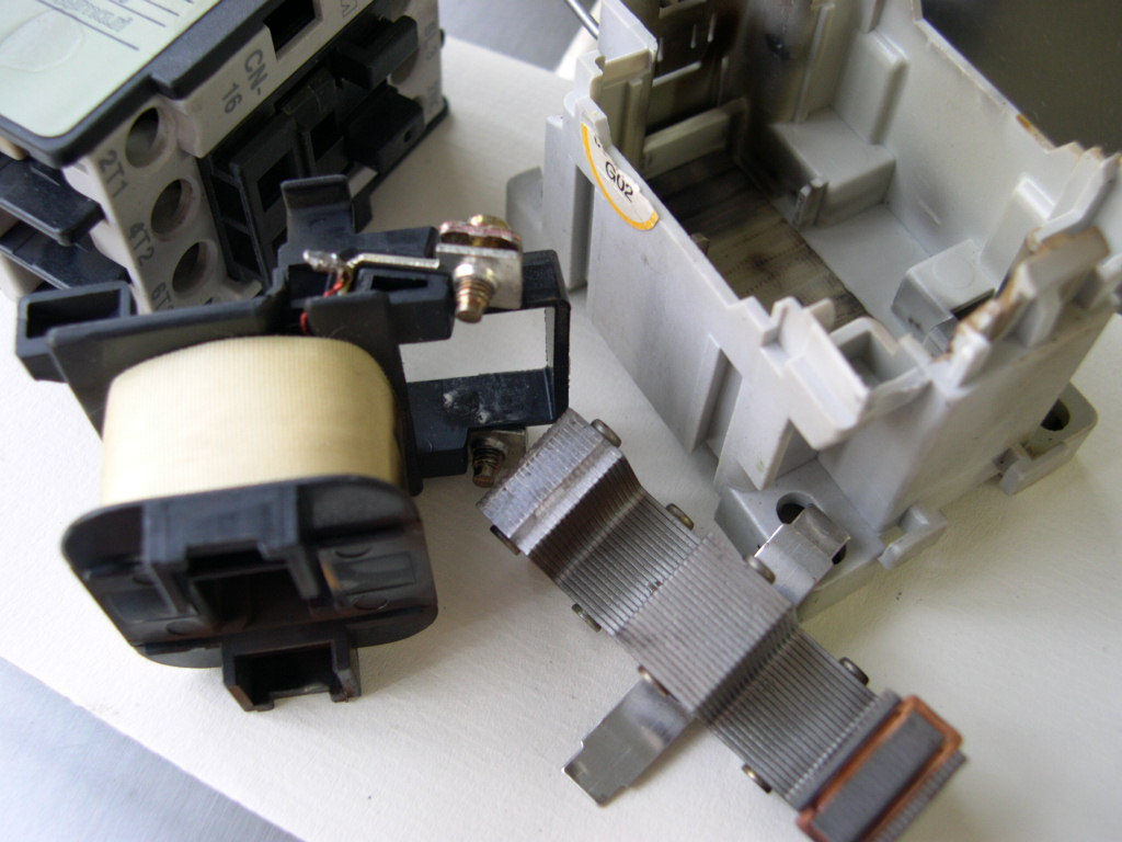
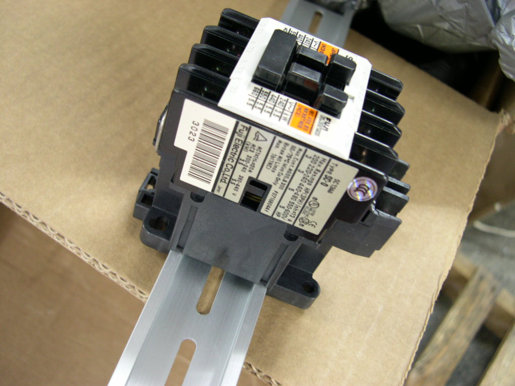
So here is a basic contactor switch, the one shown is a 2700w model, 220V single phase. The bottom half of the
switch is the coil. The top half of the switch contains the switching contacts and the armature that moves when the
coil is energised. This MCS is 8cm (H) x 8cm (D) x 4.5cm (W).
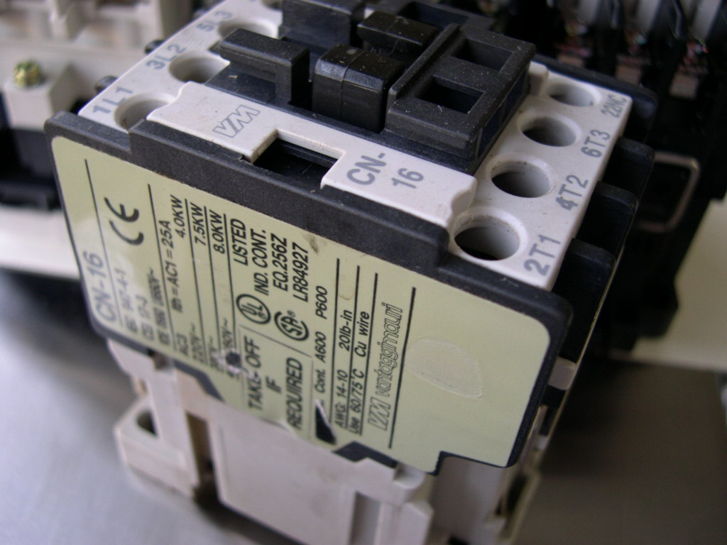
This switch, which I believe is typical of most contactors has the following wiring set-up. Remember we have wired
this based on a Normally Open switch.
A1, A2 AC Input
L1, L2, L3 One row of contacts
T1, T2, T3 Second row of contacts
21NC, 22NC Normally closed switching contacts
For example the AC input which is controlled by the p-stat goes to A1 and A2. These are the contacts that go to the
magnetic coil. The L's and T's are the switching poles. For example L1 to T1, L2 to T2 and L3 to T3. In actual fact
most coffee machines will only use 1 or 2 poles so you would usually have at least 1 spare set.
The NC switch is the normally closed position. So this is working the opposite of what we require. When the coils
are not energised (e.g. steam boiler pressure is at optimum and p-stat is OPEN) this circuit is closed. If you were so
inclined you could wire up an LED to your machine that would illuminate when the contactor is OPEN meaning that
the steam pressure is OK.
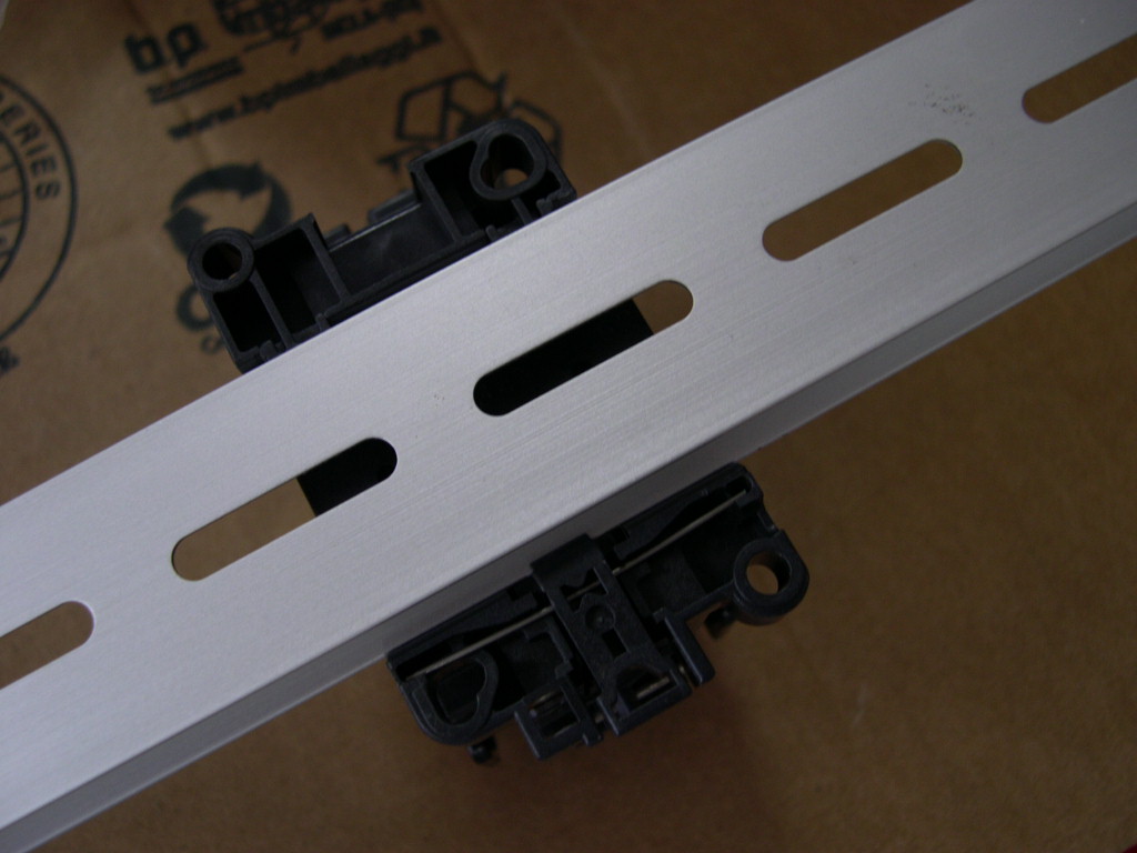
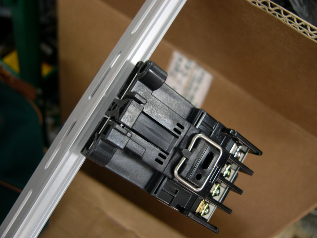
Mounting a contactor
Contactors can be mounted using two methods. The first and easiest is to use the DIN rail fixings on the base of the
unit. The contactor should have the correct fittings for the rail and pops on and off easily. If you are retrofitting a
contactor (for example if you changed from Sirai to CEME p-stats) then you will need to drill holes and secure the
small piece of DIN rail. But once you have done it you can swap out contactors with ease.
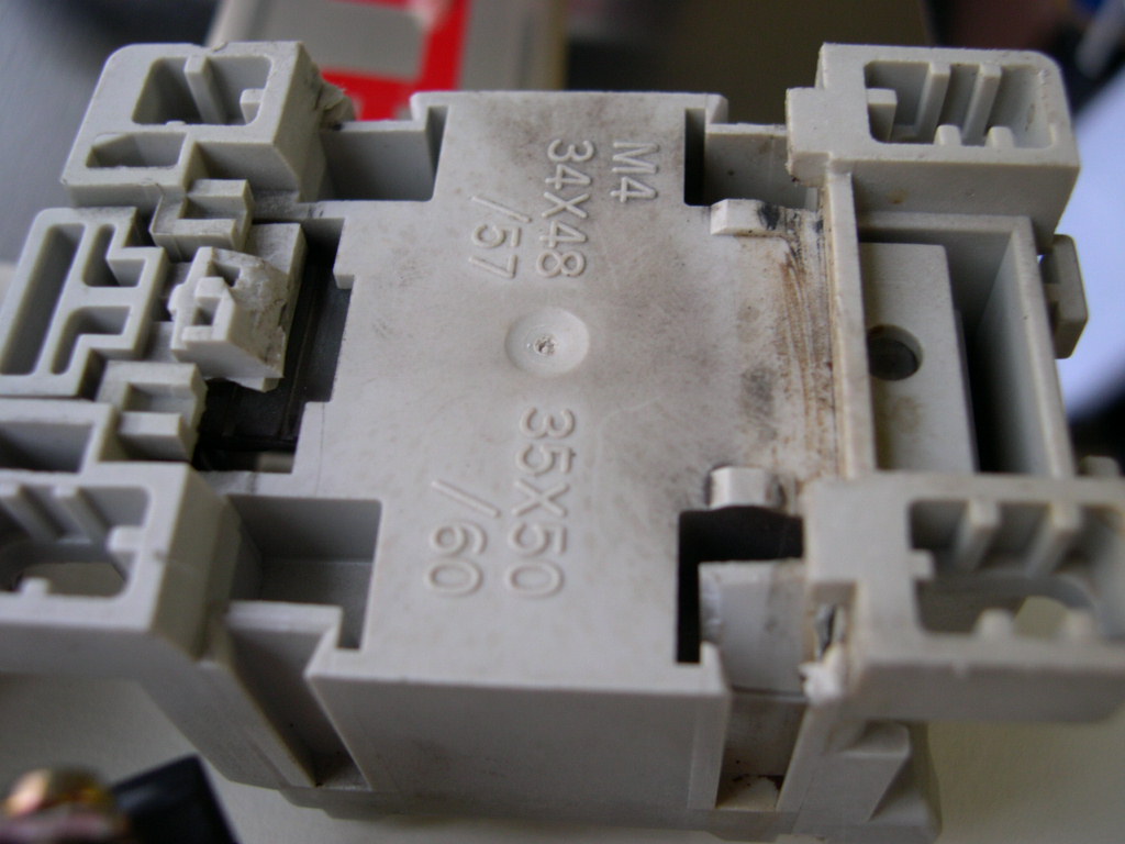
A word of caution. Not all contactors or DIN rails have the exact same dimensions - I am talking fractions of a
millimeter here. You should be cautious if the contactor when it is mounted has too much "play" i.e. it wiggles about
a bit. It shoudn't because the spring loaded clips will hold it tight but it may do. By their nature the contactor when it
switches on and off will judder sharply when switched ON. I have known a contactor free itself as the plastic mounts
snapped off. Not a good thing.
The only other way to mount it would be to drill holes and then use nuts and bolts through the holes on the bottom.
The disadvantage of this is that it would take longer to replace, but the advantage of this is that it is safely secured
and won't wiggle free.
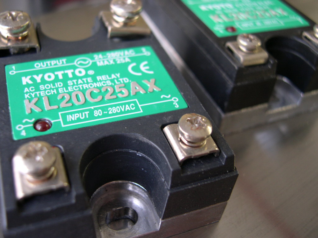
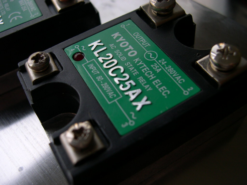
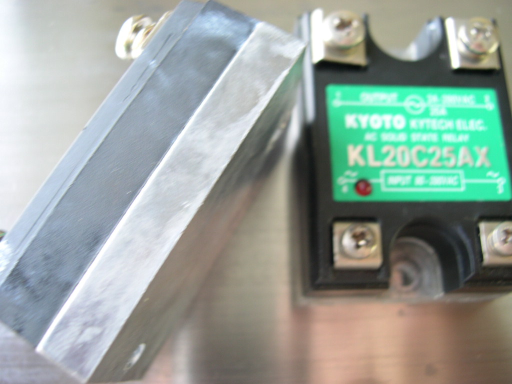
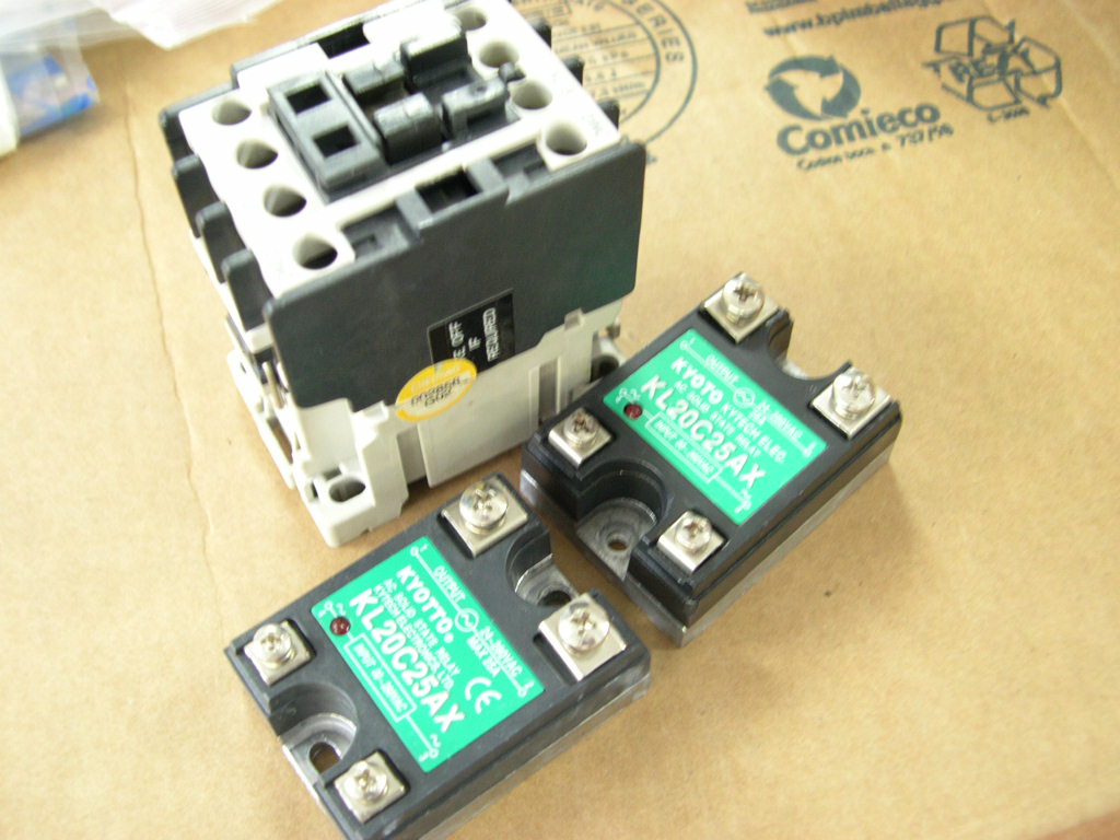
If you managed to trawl through the link above on the website you can also search for Solid Sate Relays. To sum
up in a few words the difference between the MCS and the SSR the MCS has an armature that moves (and clunks)
whereas the SSR does not and it is silent when switching. The SSR in the picture is 2cm (H) x 5.5cm (D) x 4.5cm (D)
so it is a lot smaller than the MCS.
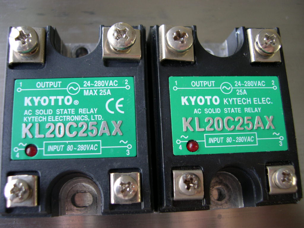
There would be 2 types of SSR used in coffee machines. You could substitute the MCS and replace it with a
suitably rated SSR. Therefore you would be using an AC Input and AC Output model. You can get either 220V or
110V AC Input.
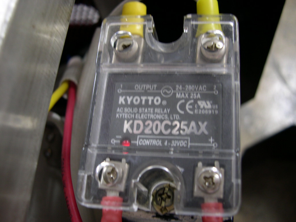
On the other hand if you are using a SSR in conjunction with a PID controller then you would be using a DC Input
(because you will be using a PID controller with SSR driver) and AC Output. To go even more specific you would be
using a Zero Crossing SSR. Zero crossing means that even though the input is on, the switch or output side will
not switch unless there is a current through it.
Both these types of SSR have 4 contact terminals 1, 2, 3 & 4.
1, 2 Output
4, 3 AC or DC Input
So if we take for example using a SSR with your steam boiler heating elements. You would be using an AC/AC SSR
and therefore the AC Input (controlled by the p-stat) goes to terminals 3 and 4. If you are using the SSR with your
SSR driver output PID controller then you would connect the DC output from the PID to an DC Input, AC Output
SSR. In this case polarity is crucial so follow the polarity signs in the PID manual and on the SSR itself.
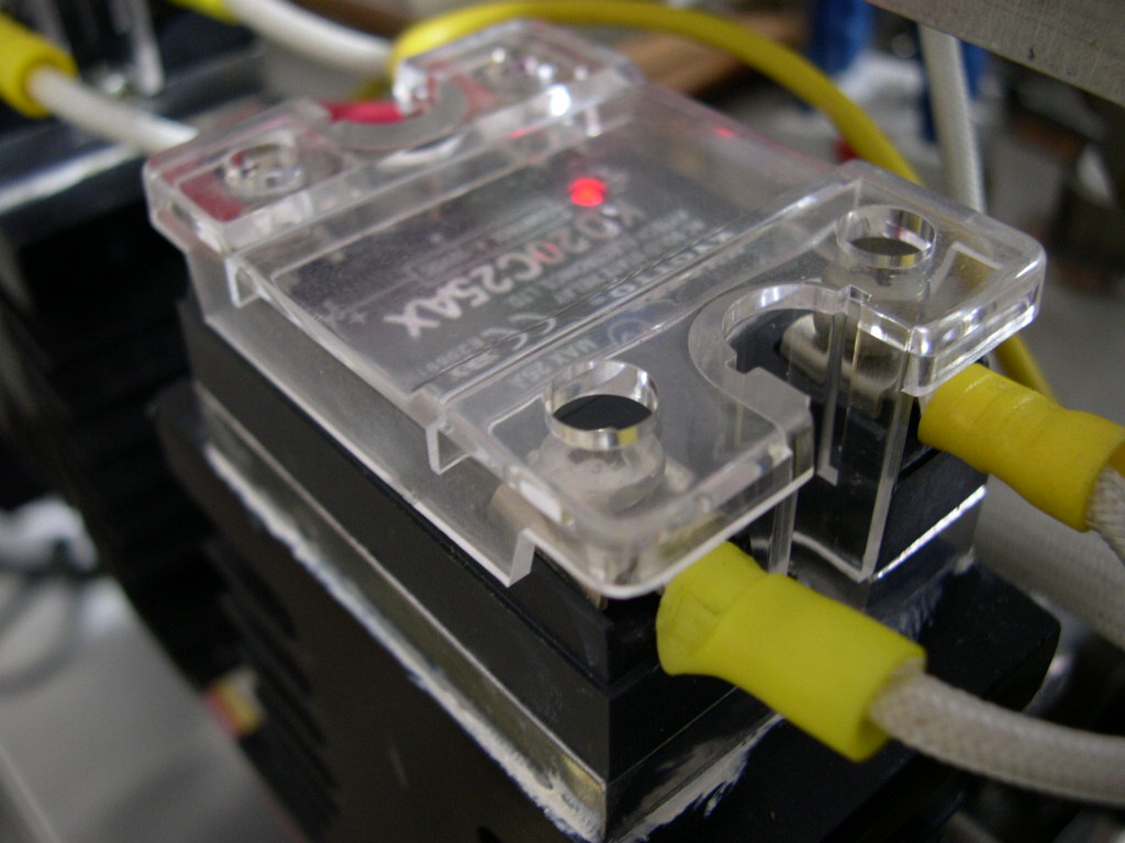
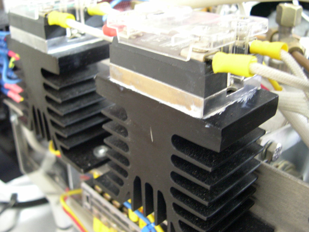
A word of caution, the small size and the solid state technology of the SSR comes at a price. They do not like heat.
Considering the fact that they produce heat and we are using them in coffee machines with high ambient
temperatures is a drawback. Therefore we need to use a heat-sink to help the SSR radiate the heat away from
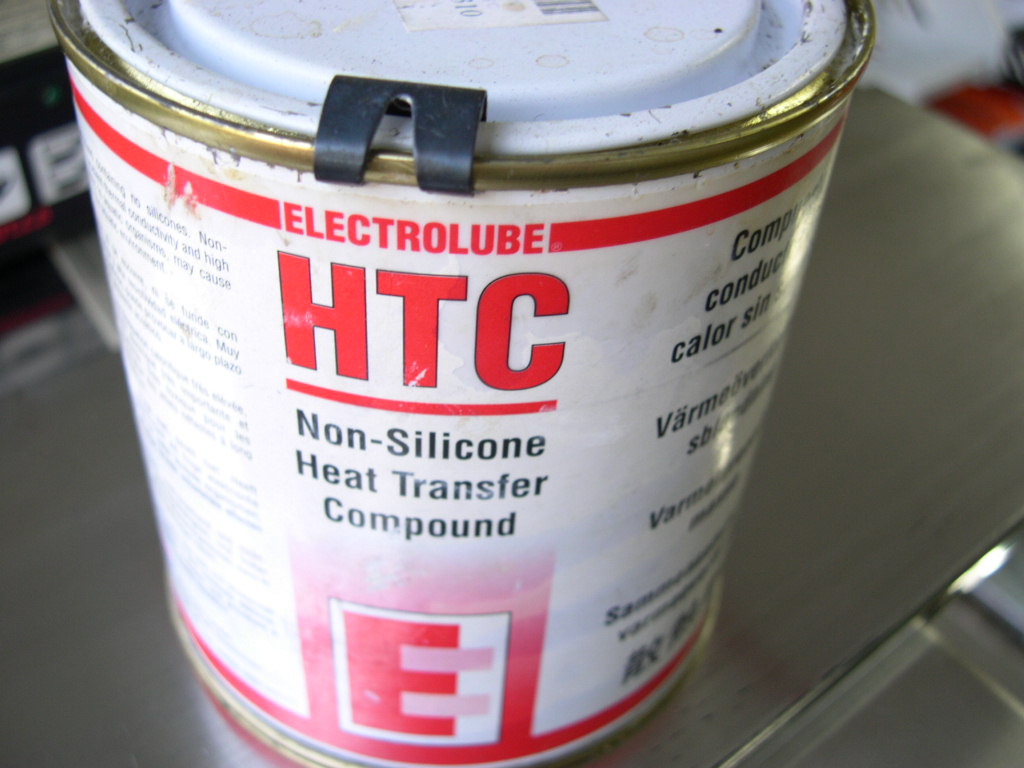
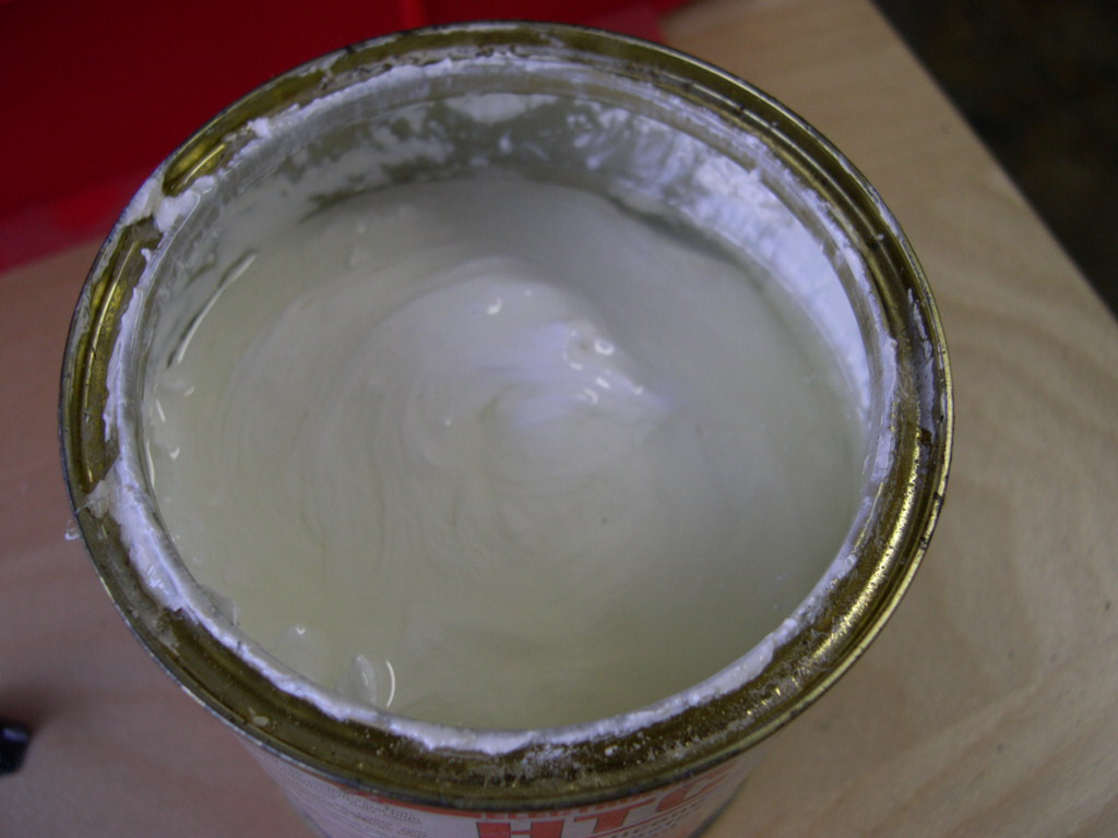
itself. To help even further it is recommended that we use a heat transfer compound between the aluminum base
of the SSR and the aluminum heat sink.
Incorrect heatsinking is a problem and it will cause your SSR to cut out and need replacement. I believe that Isomac
owners suffer from this due to lack of any heatsink installed at the factory.
Please note that in order to achieve the rating of your SSR e.g. 25amp you must use a suitable heatsink.
If you do not then the rating is dramatically reduced. For example a 40amp without heatsink is only rated
to around 10amps.
will say yes, but please ask first!
Email me here.