The Espresso Machine Restoration site
A non-commercial site for those interested in espresso equipment repair and restoration.

Part 2
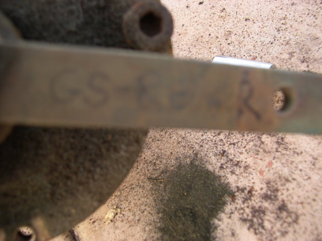
Of course the most unique feature of this machine has to be the group. It`s predecessor the GS series had
re-written the rule book. It was the first commercially produced machine to feature two separate boilers - one for
steam and one for coffee. In fact it would not be too far fetched to say that the importance to the company of the
GS series is the same as the wonderful E61 machine to the Faema company.
As far as I could ascertain, the GS and GS2 models left the factory with either a manual group (this machine) or with
a solenoid group. The manual group is by far the most unusual and many believe it to be the best group before or
since. The manual group (aka Paddle group) is operated solely by the barista, there are no electronic valves.
Again very similiar to the E61. The group essentially has 3 positions. Imagine a clock face and we are looking at
the group from above and that the barista side is 6 o`clock, customer side is 12 o`clock.
The first position is when the paddle is at 4 o`clock. No water may enter the diffusor block from the group, but at
this position the path from the coffee grounds to the relief drain is open. So after you make a shot in this position
the pressure from the coffee is relieved.
The second position is around 8 o`clock. As you turn the paddle clockwise between 4 and 8 there is nothing. Then
suddenly at the 8 position the valve will open that allows water to exit the group and hit the coffee. But at this stage
the pump is not activated so the water is moving under boiler pressure alone.
The third position is reached by pushing the paddle ever so slightly past 8 and you can feel the microswitch `bite`.
The pump will therefore switch on.
Pre-infusion
The advantage that this group enjoys over a solenoid group is in the ability for the operator to pre-infuse the coffee
under boiler pressure for as long as he/she desires. Many believe that the gradual build up of pressure on the
coffee results in a far better shot than zero to full pressure. Pre-infusion may be done two ways, either manually as
in this group (or an E61) or it may be done electronically. Electronically means opening the solenoid valve but
delaying the switching on of the pump.
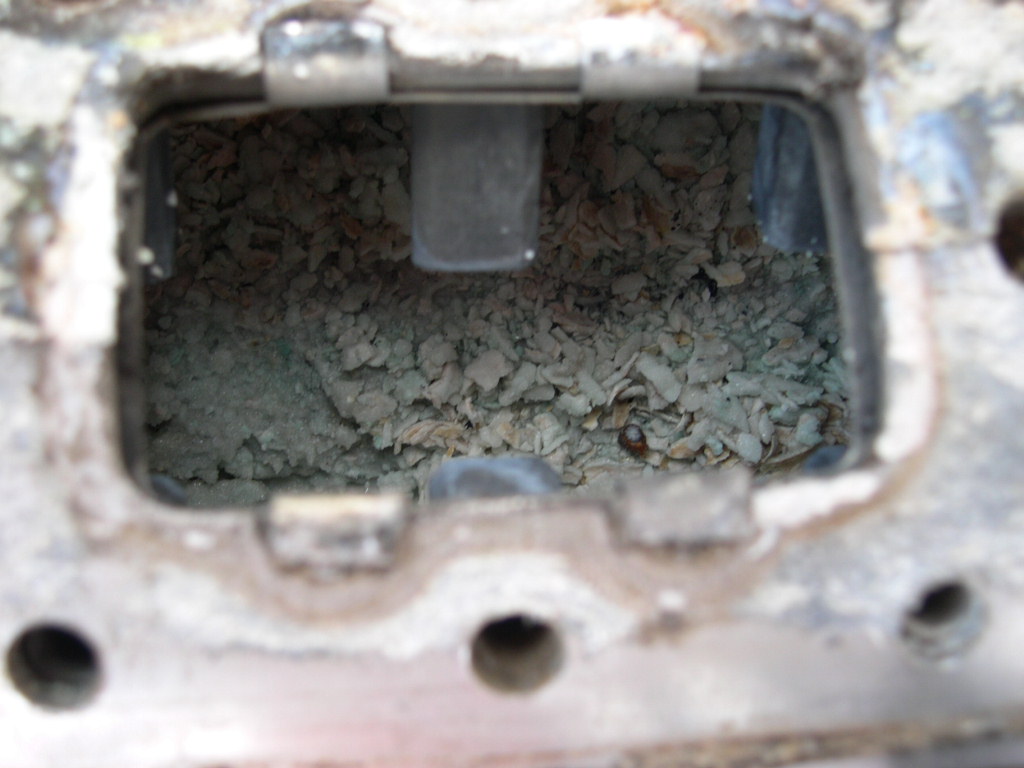
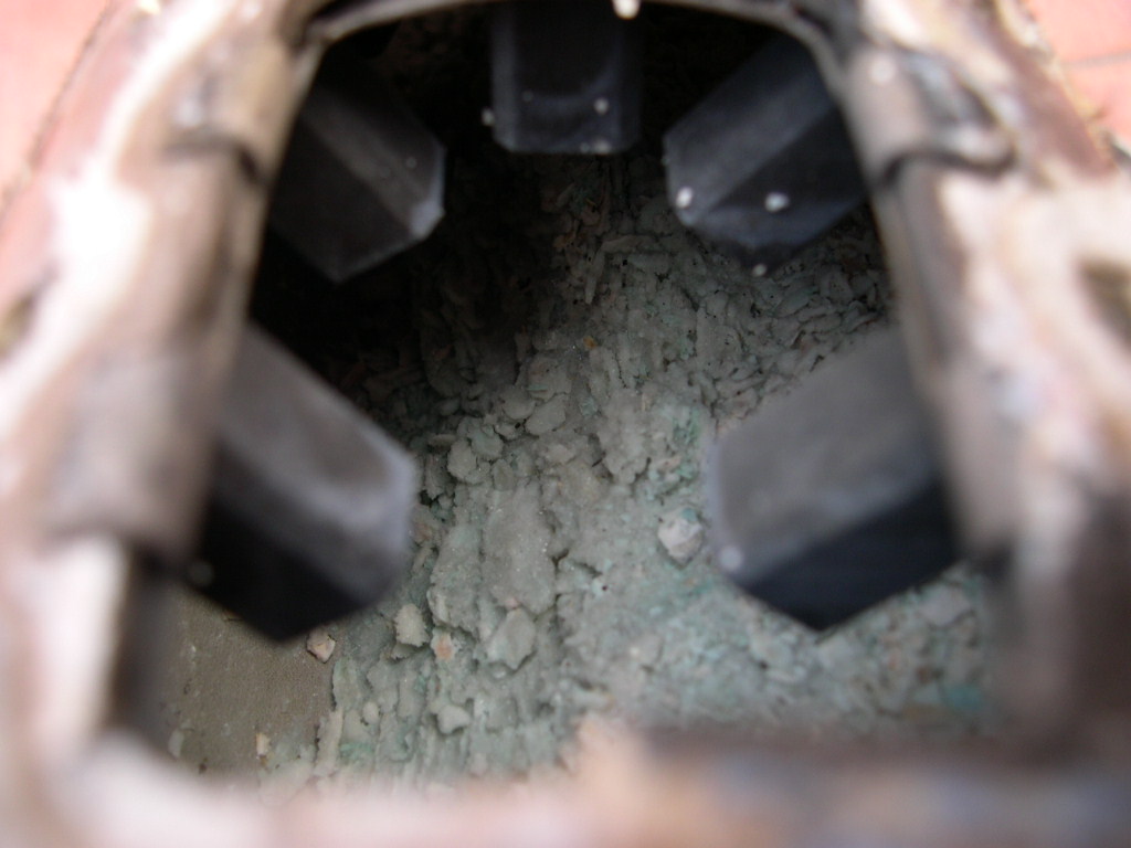
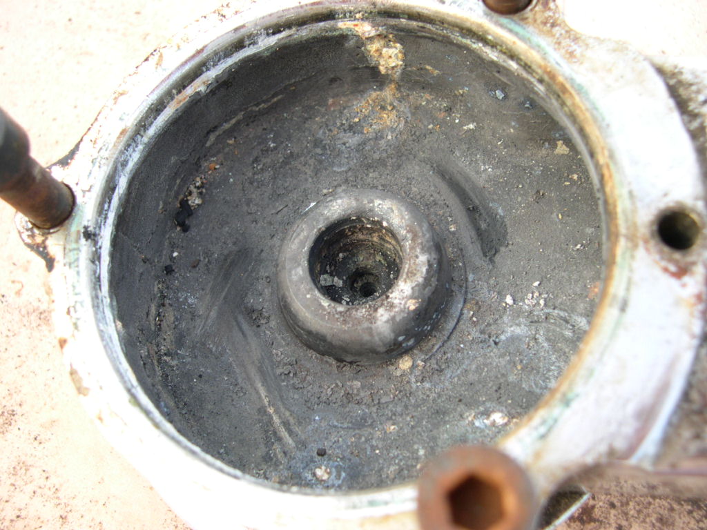
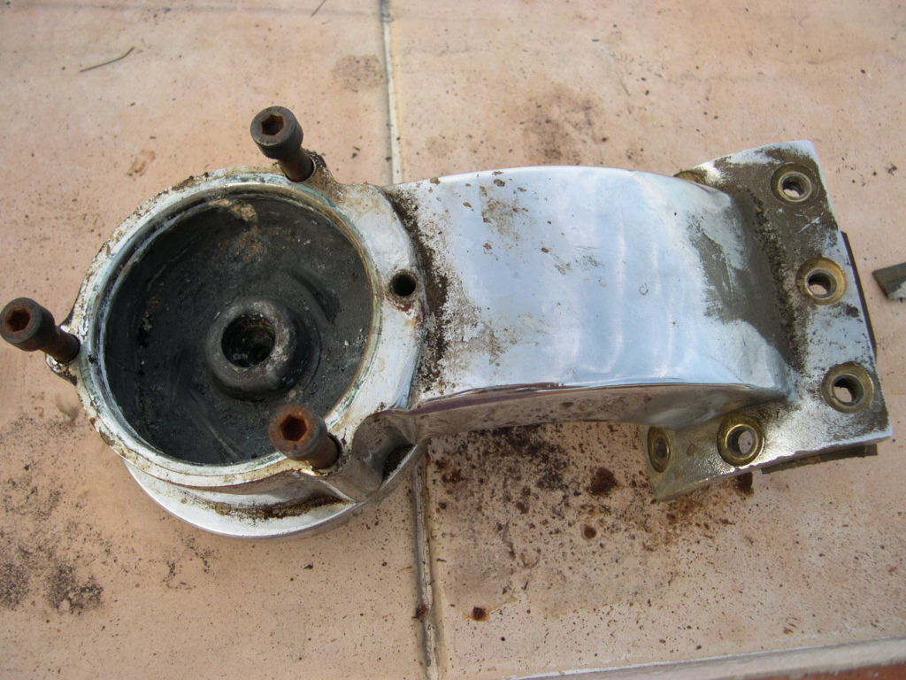
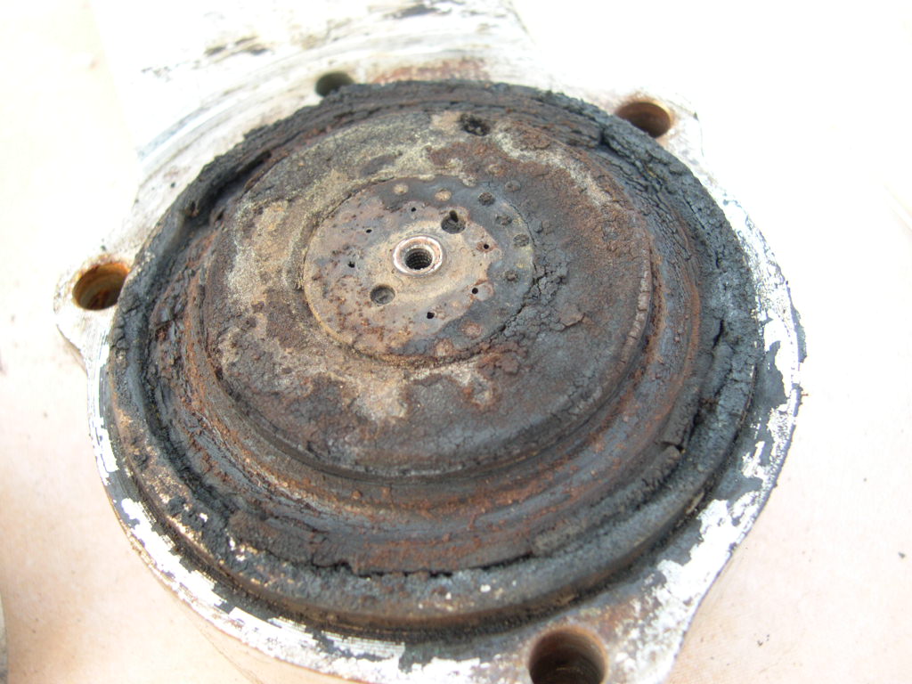
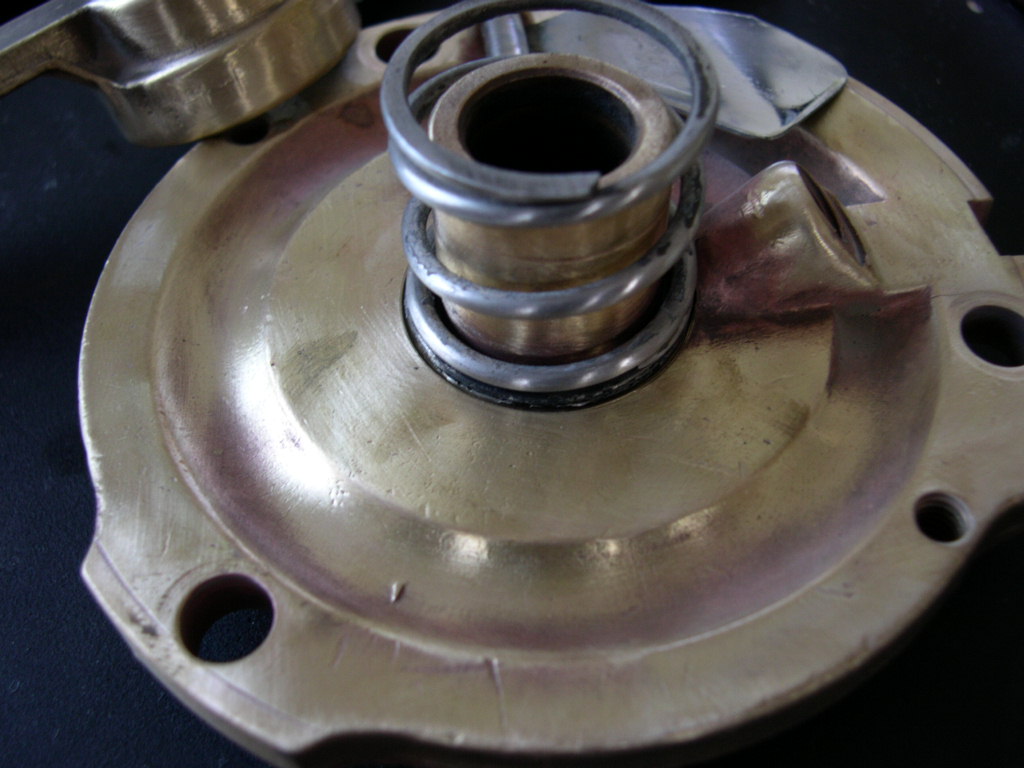
shocking but would just take time. I never ever imagined what I was about to discover. Usually the groups, even
after you have removed the 8 retaining bolts, are stuck to the boiler with the paper gasket acting as a weld. Not
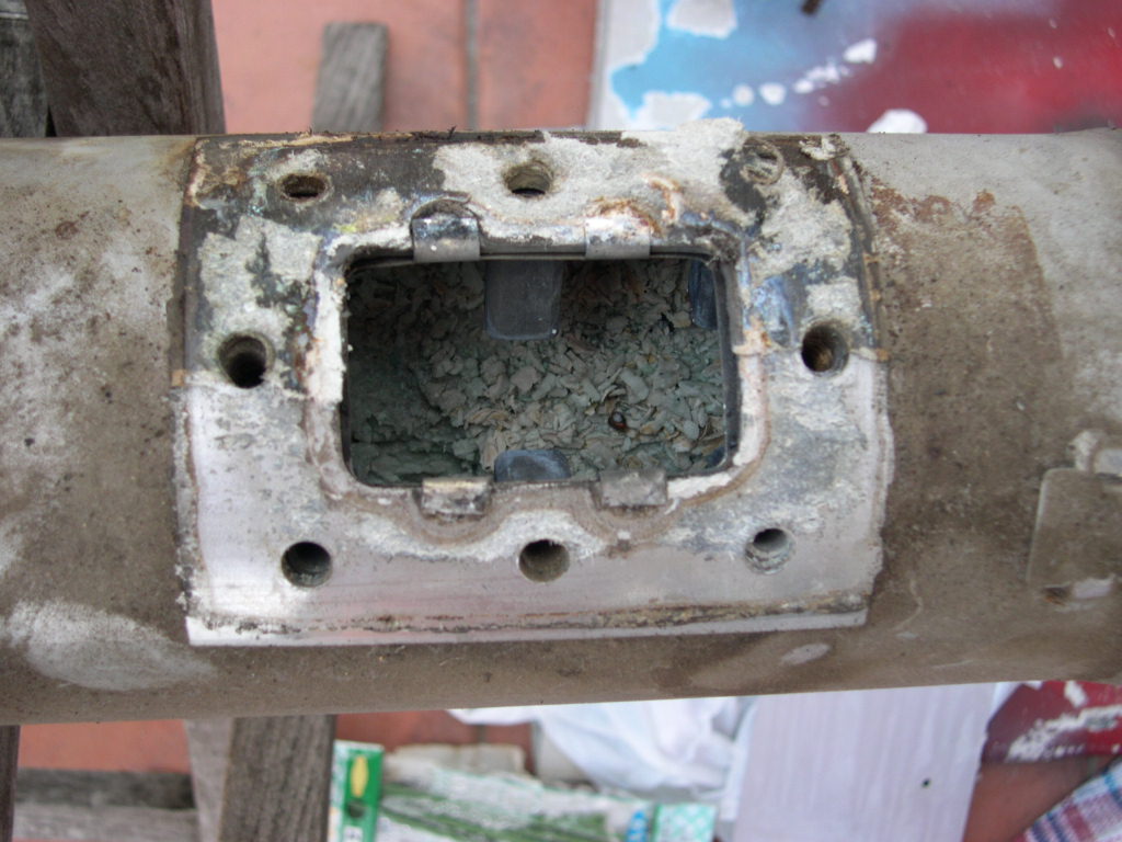
these babies, above I mentioned that they came off rather too easily. The reason soon became apparent.
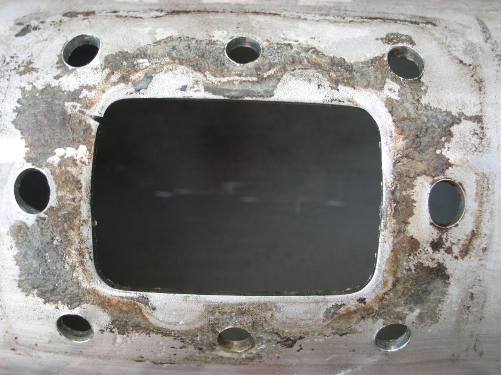
mount broken but the boiler shape had changed. So much so that there was a definite bulge
on the middle group and that the holes had become oval. Anyway I descaled it and had to
think on this since it was a rather serious setback.
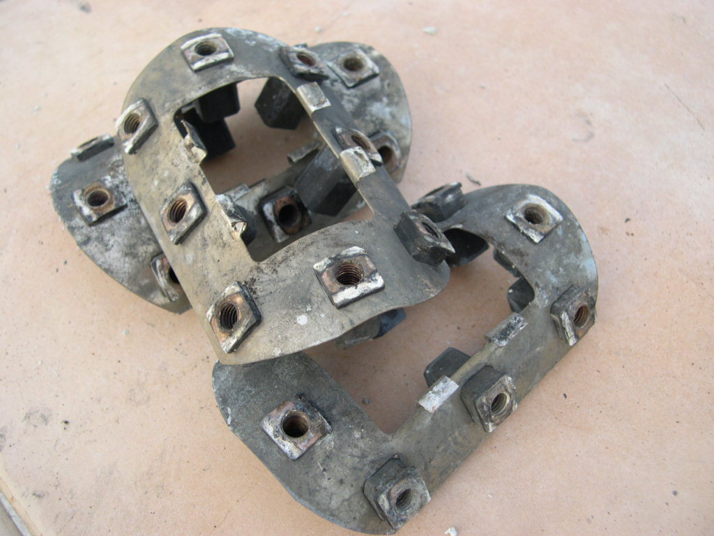
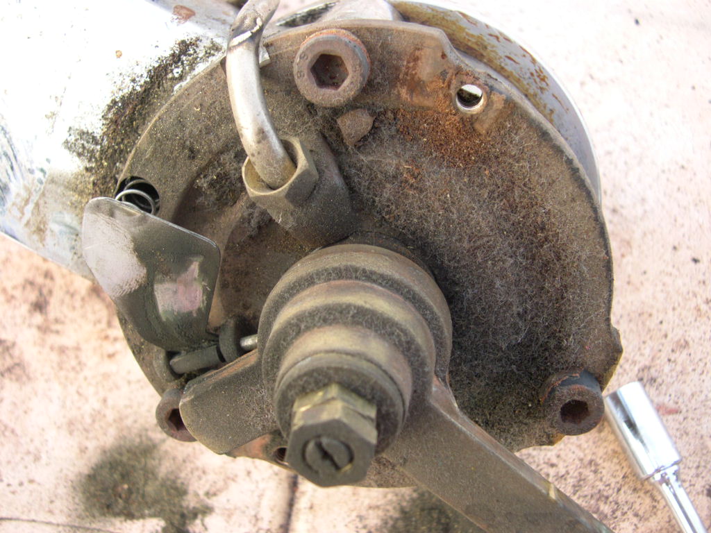
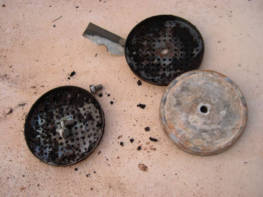
The factory in Florence gave me one piece of advice. Try not to take the groups apart! Oh well by that stage it was
too late and besides how can it be a total restoration if you don`t clean everything? Their main concern was that
even when using new parts many years ago, the manual groups were very difficult to assemble and get to work
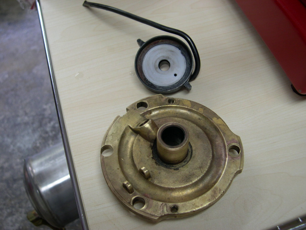
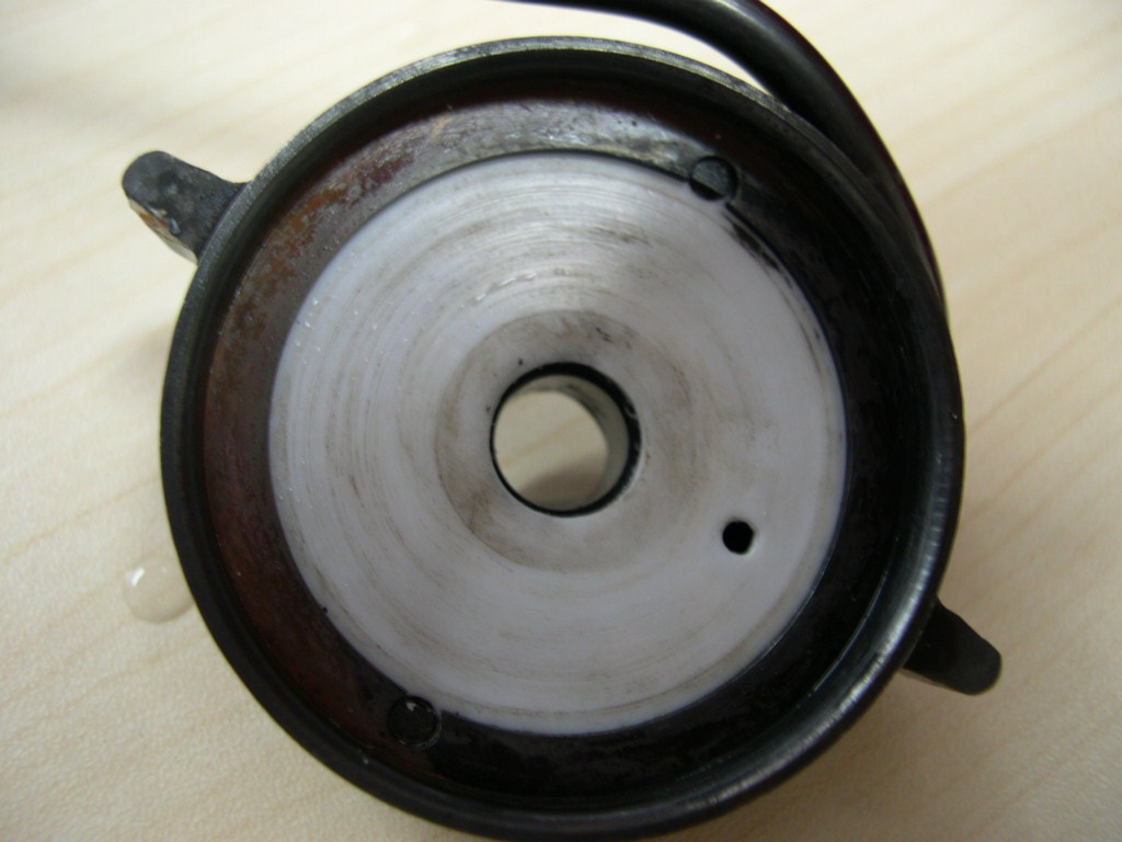
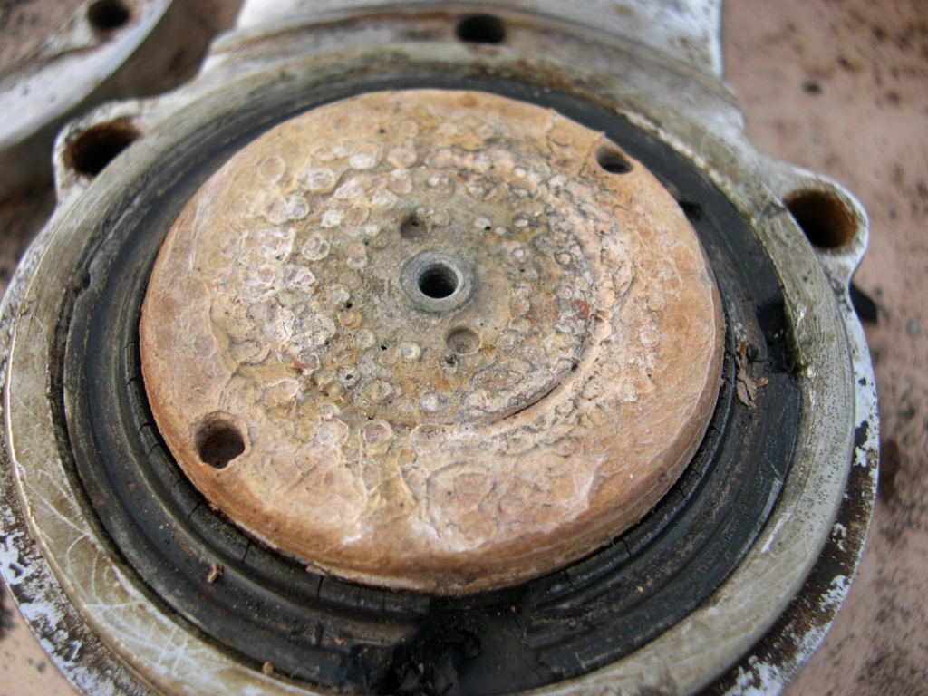
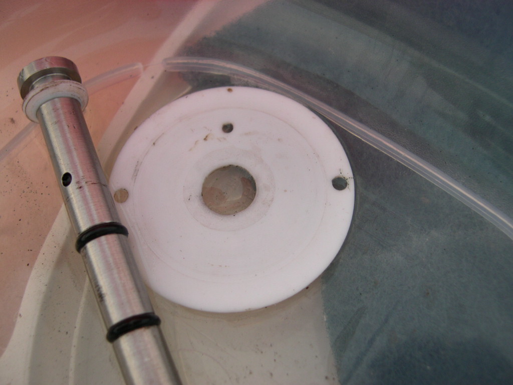
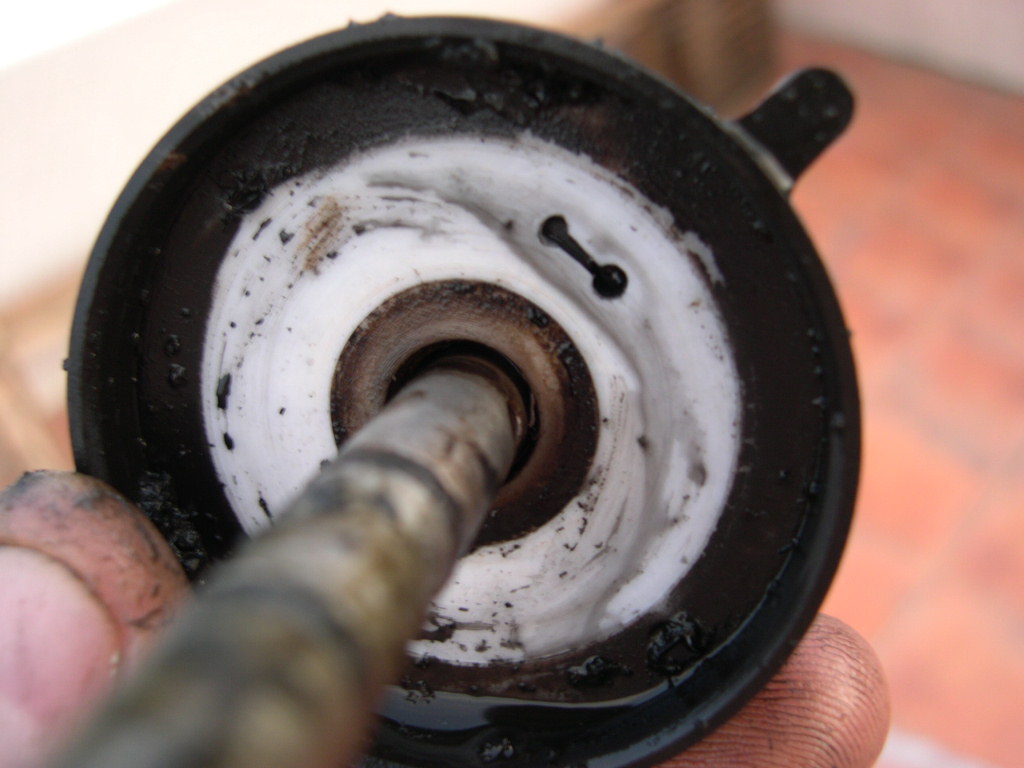
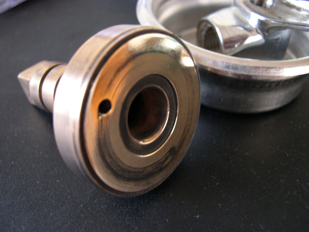
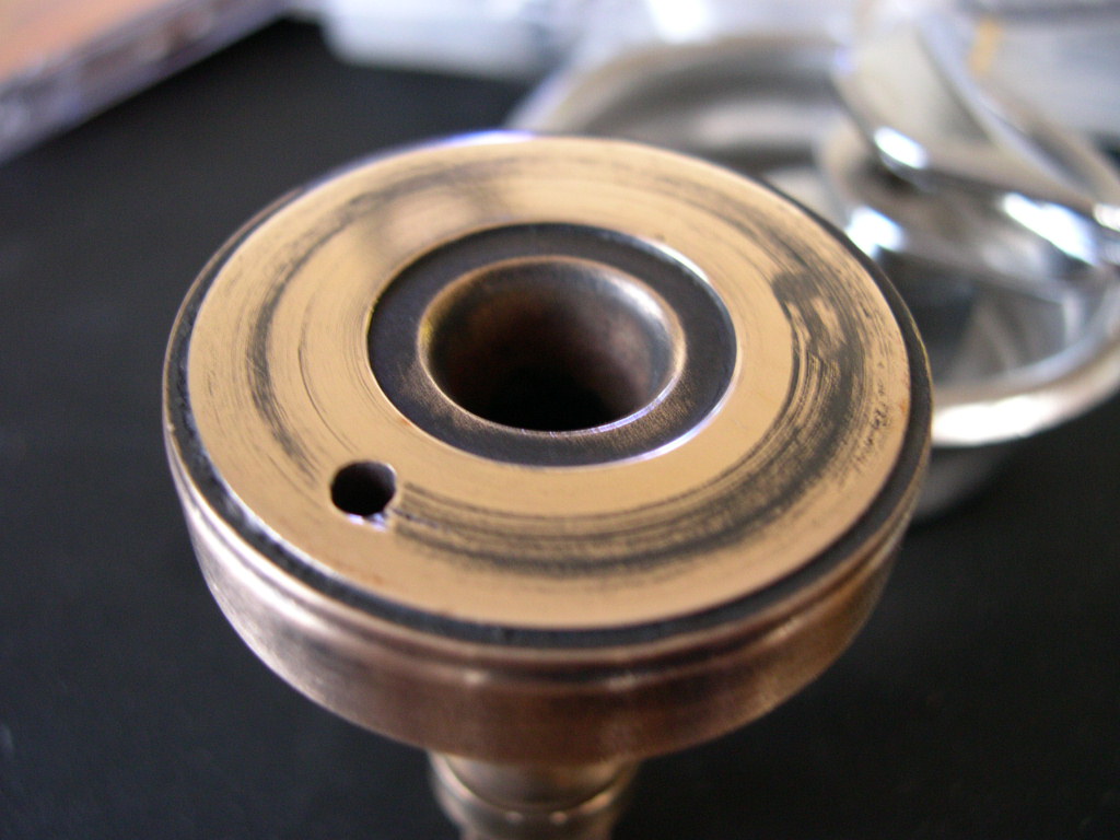
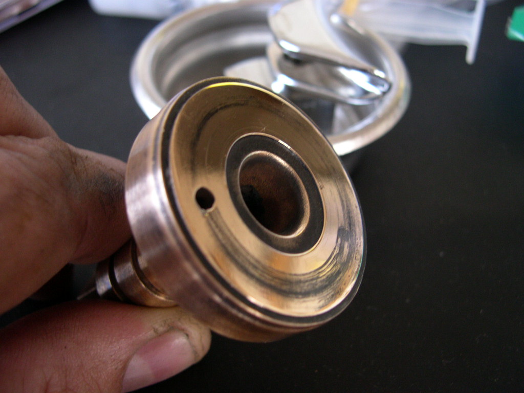
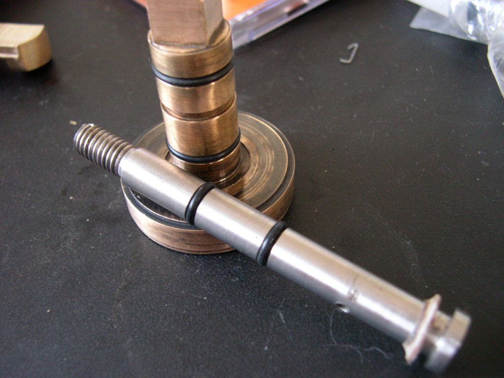
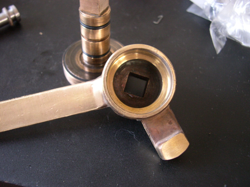
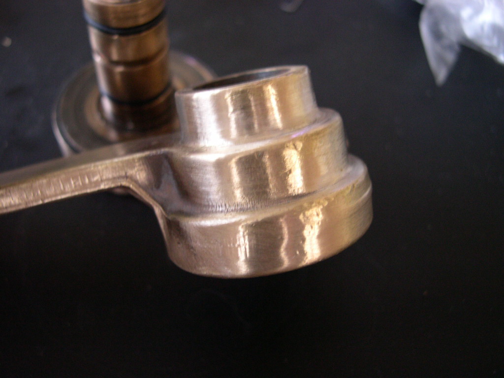
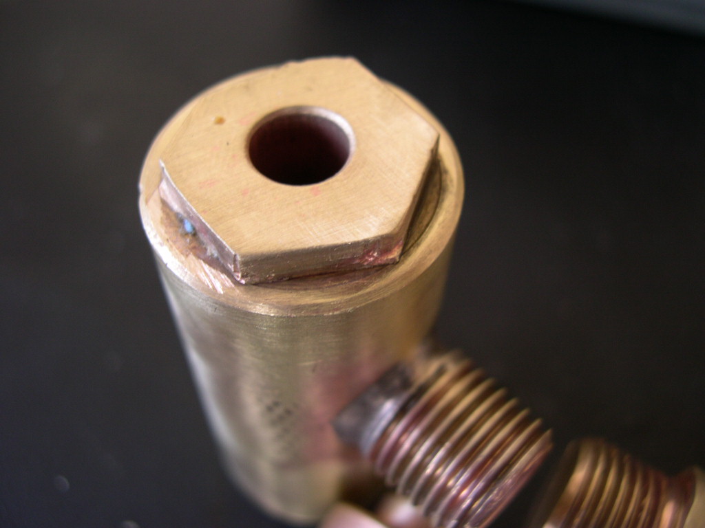
properly. Of particular importance was the fact that the bronze part (resembles a tamper) needs to be highly
polished and scratch free. The polished section is required to mate and seal with the teflon discs. Any kind of
scratch on either the bronze or the teflon and the groups will not work. One of the groups in fact had a large patch
of pitting on the bronze. Rather than have a group that I could not use I repaired it on a lathe by turning and later
polishing so that the surface was true and polished.
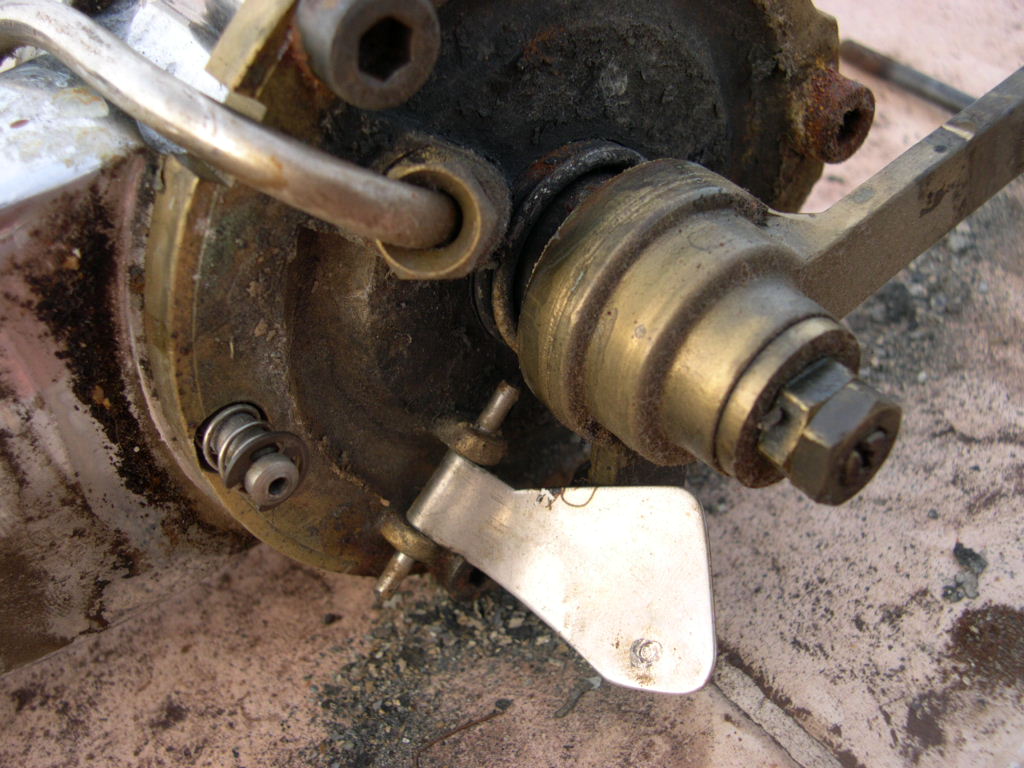
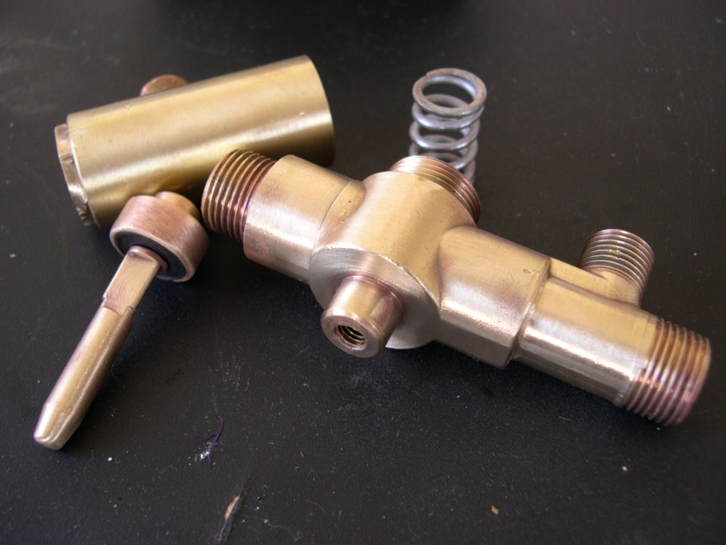
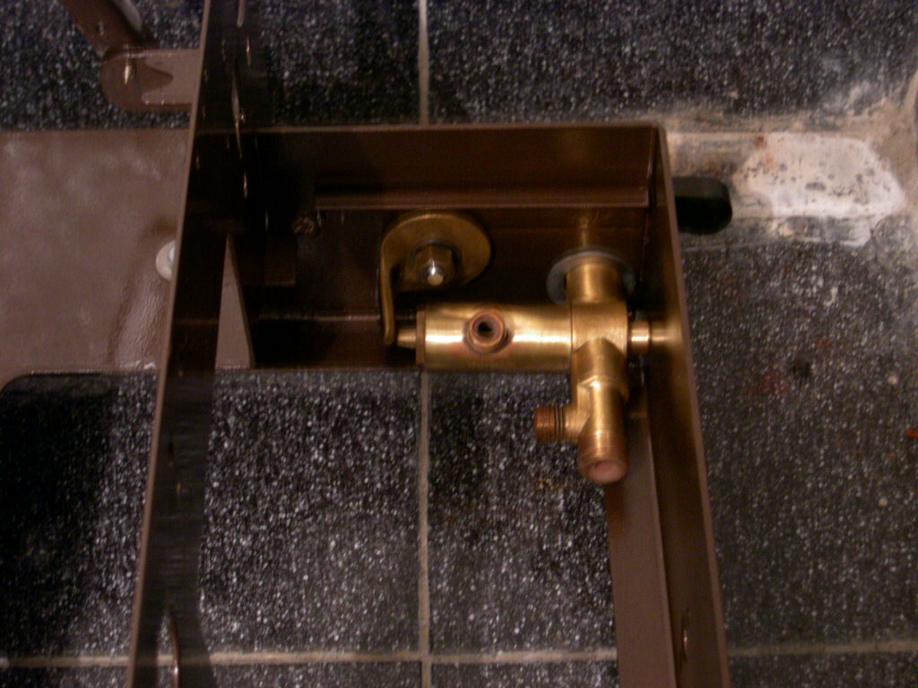
The machine even though it has a Gicar autofil unit only has a simple on/off rocker switch. Therefore in order that
you don`t fry the elements upon installation you have a manual fill valve. On this machine it is operated by the cool
lever on the side of the machine. To open the valve you lift the lever up. When I received the machine the valve
was frozen solid by the scale and dirt. I had to completely dismantle it, descale it and then fabricate some gaskets
from viton rubber. But after I did all that it now works like a charm.
will say yes, but please ask first!
Email me here.