The Espresso Machine Restoration site
A non-commercial site for those interested in espresso equipment repair and restoration.

rebuild Part 2
As I was putting it back together I had all these bizarre ideas racing through my head. I wanted to put the Linea
back together and keep it "as factory condition" as I could but at the same time impart some small details of my own
personality.
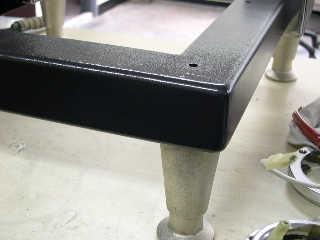
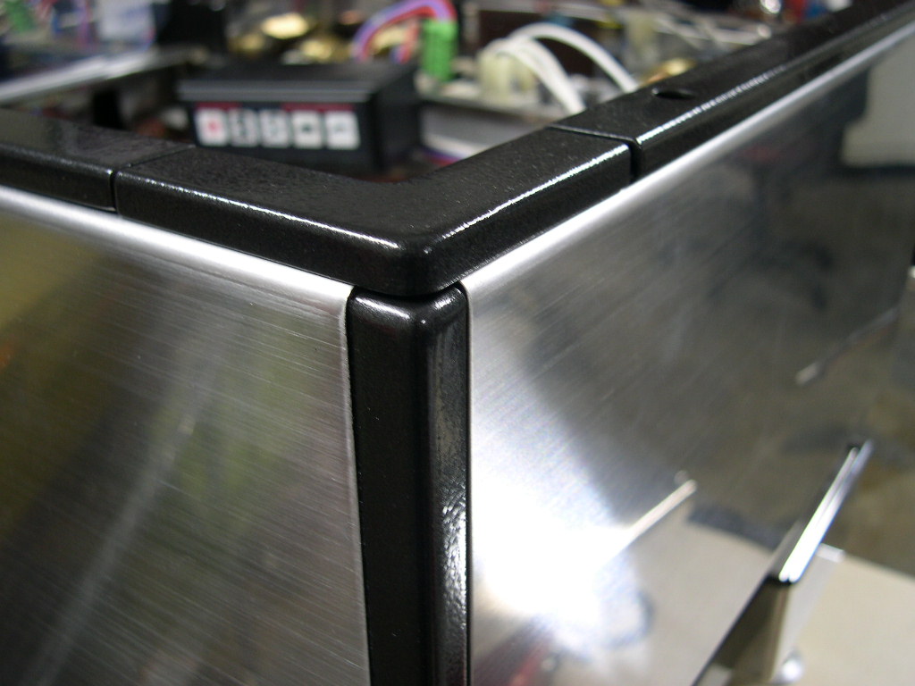
I repainted the frame and the black trim in a metallic black colour which I like very much. It has a sort of sparkle to it
which is a very subtle change over the standard black from Marzocco.
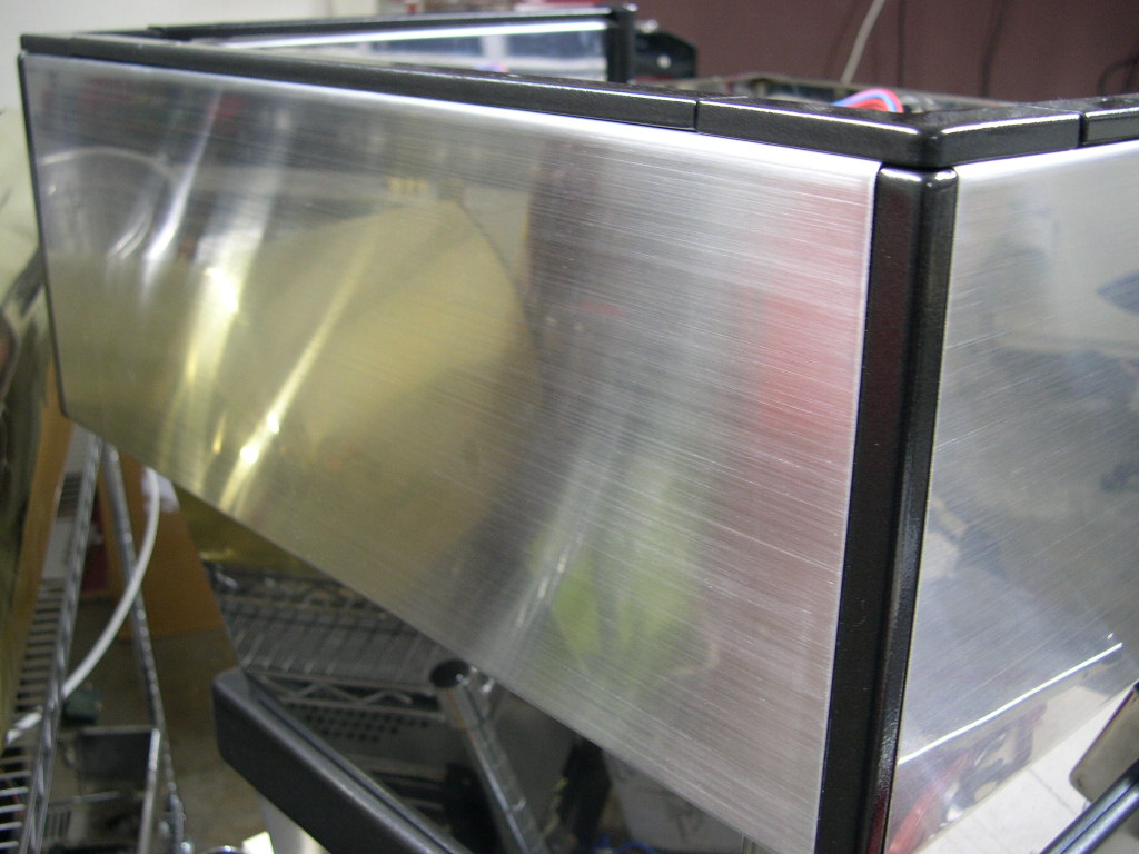
Of course all of the metal panels had to be either repolished back to their respective mirror finish or satin brushed
finish. And that also included the main body which is pictured above.
"wouldn't it be fun to try it on some other parts?".
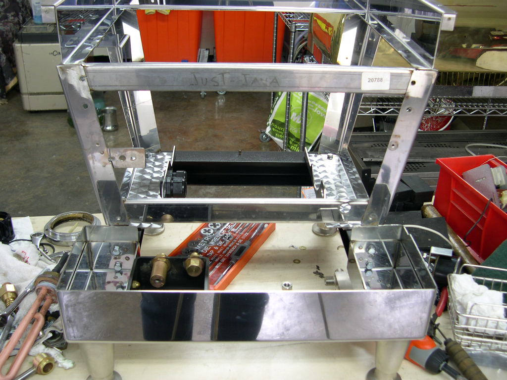
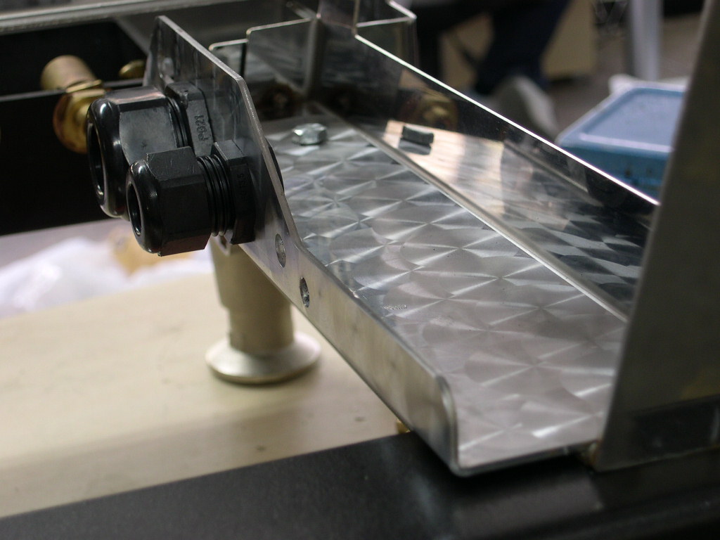
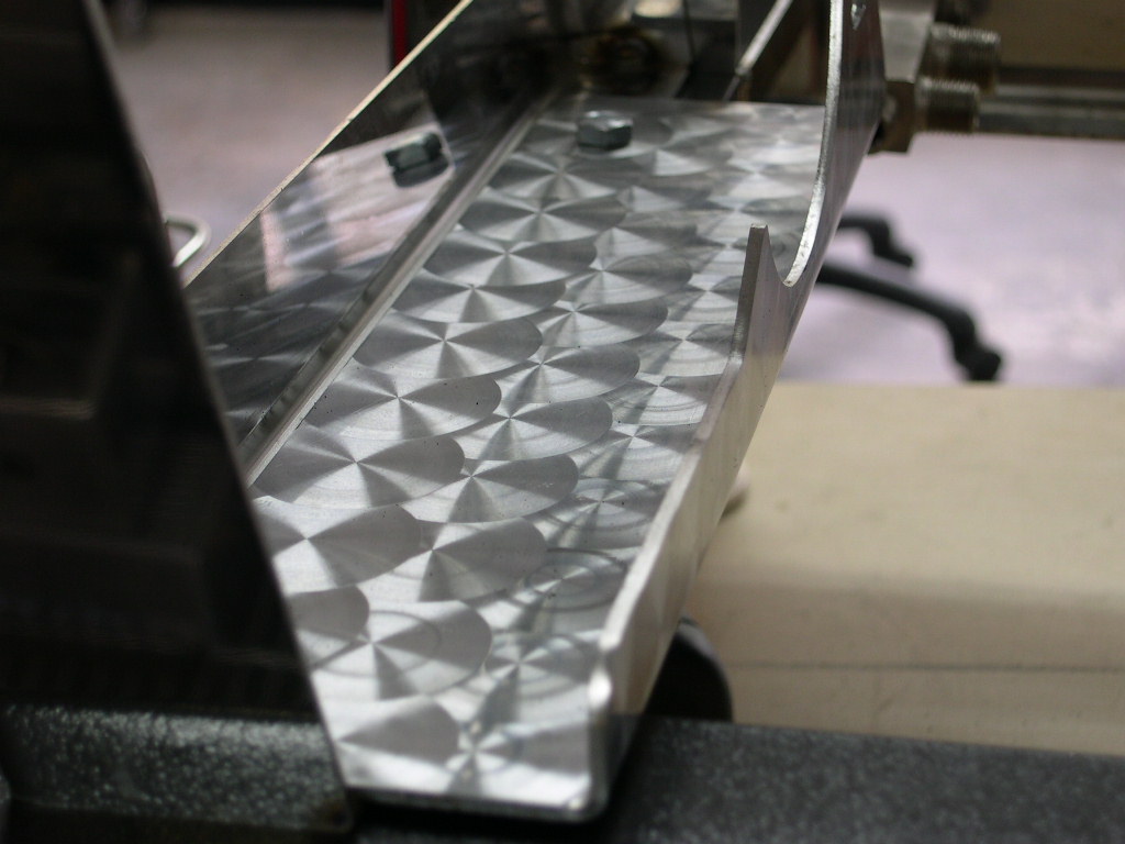
So as you can see I did my swirly pattern on the inside of the upper fascia (control) panel. It was not easy at all
since the metal was already formed. Usually these things are done when the metal is flat not when it has been cut,
formed and welded into box shapes.
Well the Sirai p-stat was replaced with the smaller CEME p-stat....
And then I got to thinking about the PID installation. The main problem is trying to find someplace to put the
controller which is a) cool (ambient temp) b) easily accessible to adjust c) out of the way.
On my P1 machine I had a space cut in the front fascia panel on it went in there. That was good but the controller
then required a cooling fan to stop is wandering.
On the 1 group Linea EE I had a space cut in the bottom footwell. This was good as it was a cool place and was out
of the way. However it was heartbreaking to cut that hole in the steel so I decided against doing that again - and
besides I was looking to have a machine that was fairly normal looking but was conceeling some dark secrets if you
looked a bit closer.
So I then thought about putting it under the machine near to where I always mount the SSR's.
thermocouple I found some pre-made ones that had a very quick reponse time it was very easy to mount into the
existing thermostat fitting (once you remove the thermostat well).
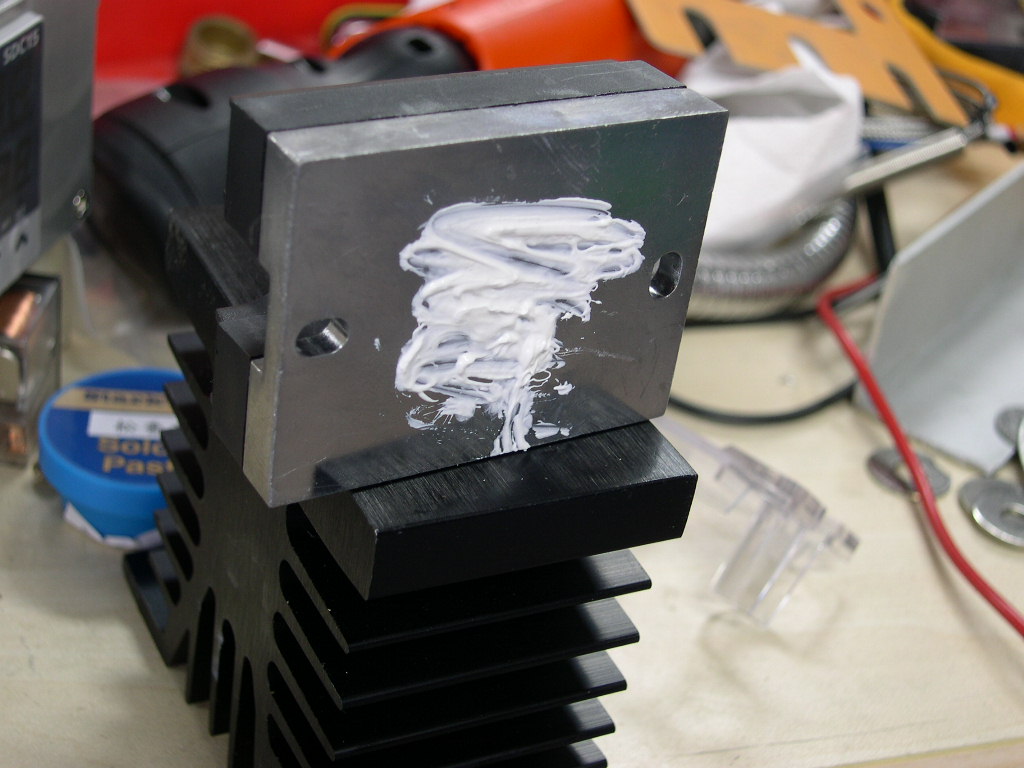
My components...
DC Input AC Output 25 AMP SSR
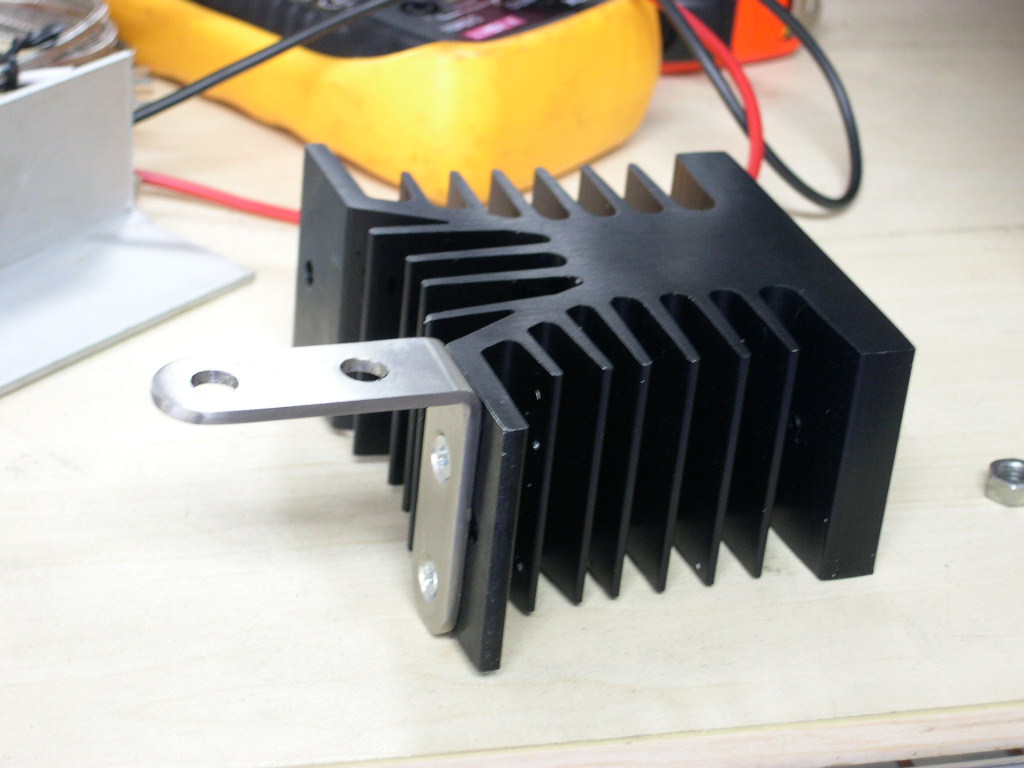
Heatsink for the SSR.
K-type thermocouple
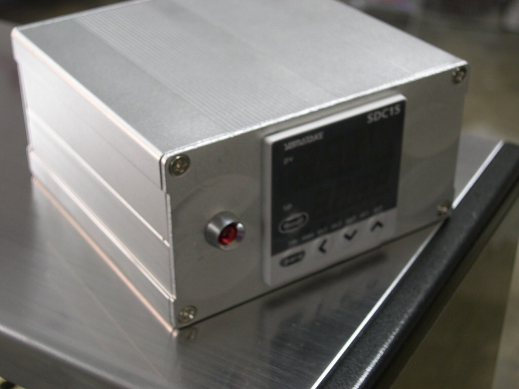
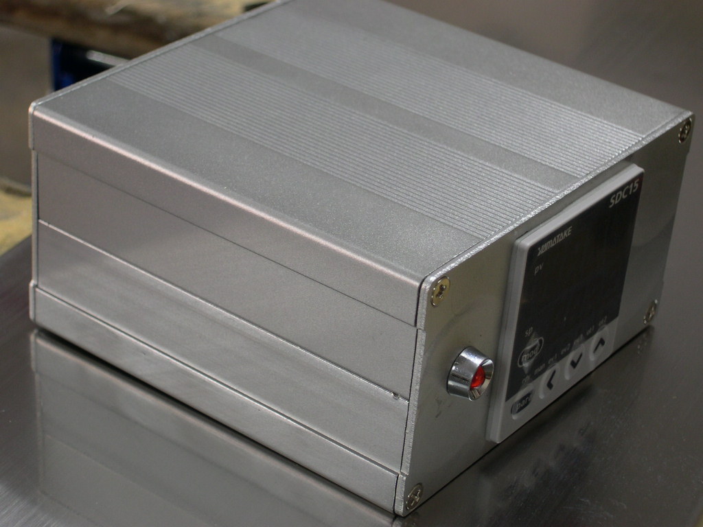
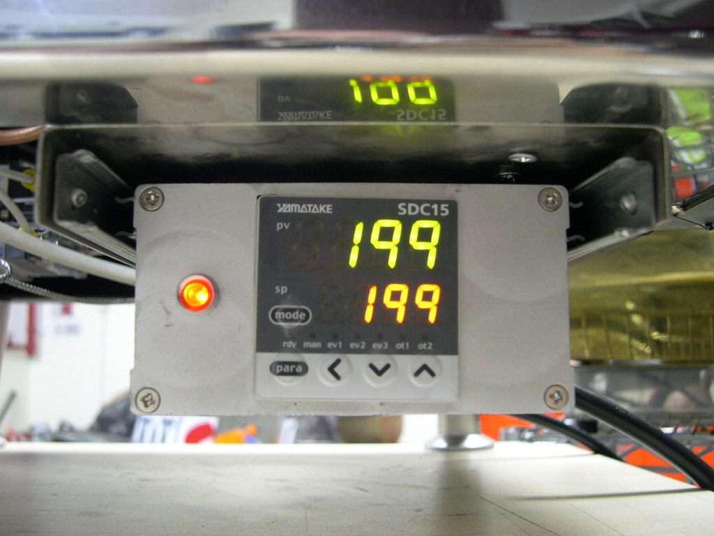
Yamatake SDC15 control unit
Aluminium case
Nowadays I have my system worked out. The SSR I always mount under the boilers and I have had some brackets
made so that I can use the existing nuts and bolts inside the frame. No need for any drilling.
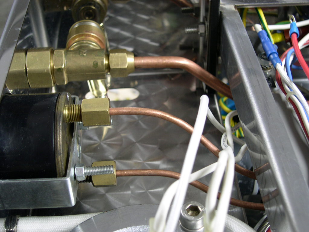
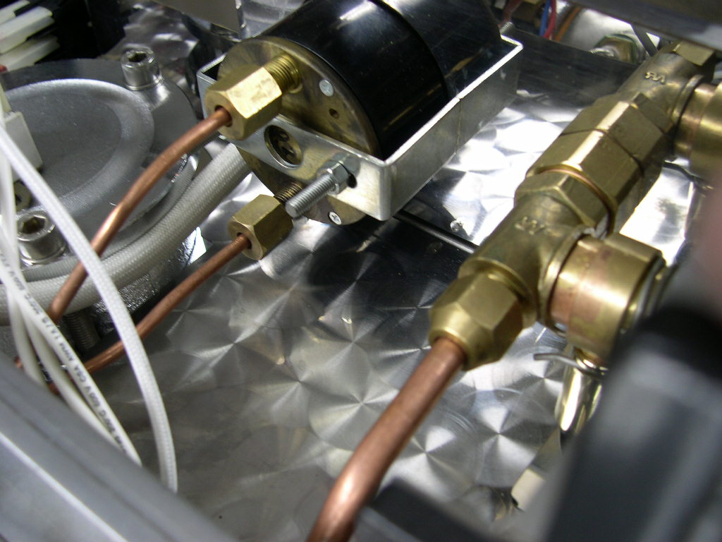
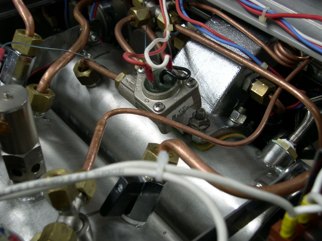
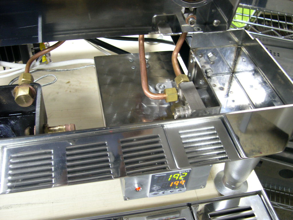
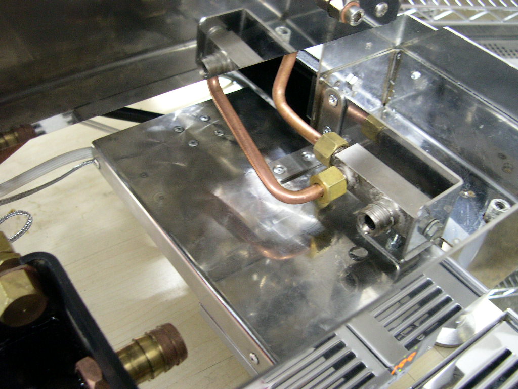
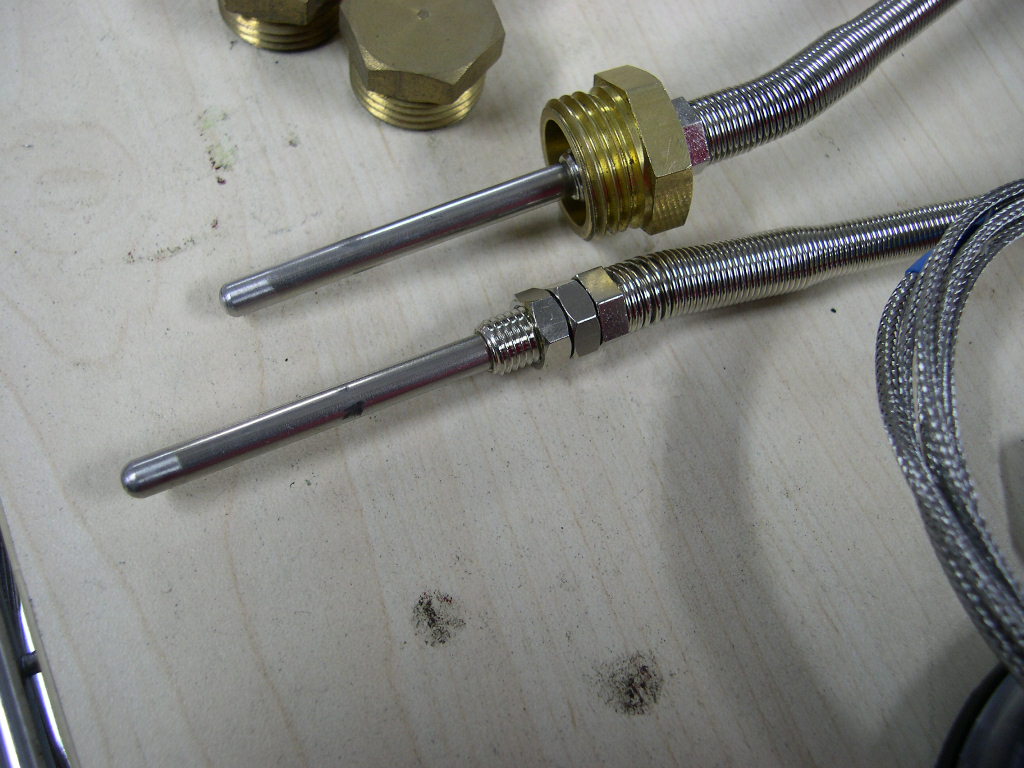
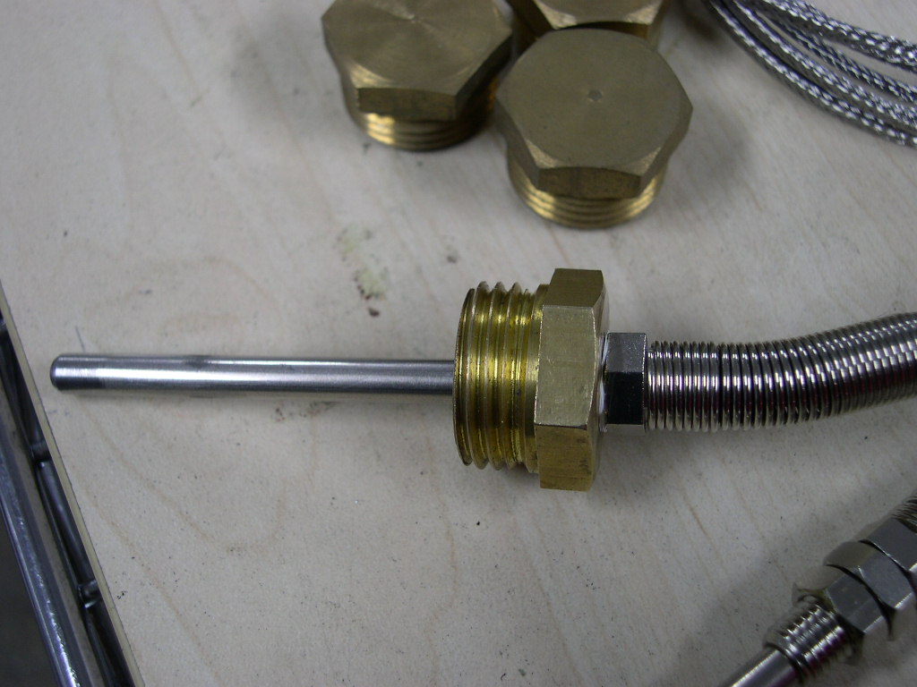
As I said above the thermocouple was pre-made and had some threading on it so all I had to do was find another
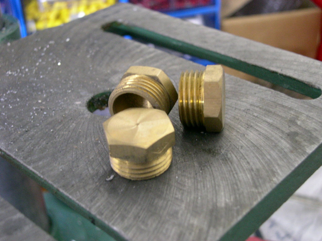
fitting to screw it into. What I eventually did was find some blank fittings that screwed directly into the La Marzocco
brew boiler and then drilled and tapped so that the thermocouple screwed into that. In the picture above you will
see the thermocouple screws into a brass fitting and for precaution I made some teflon washers out of some teflon
sheets to seal the probe and the brass fitting.
The probe was then tested up to 20 bars pressure for several hours to make sure it was safe to use.
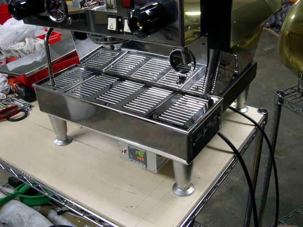
Finding a place for the controller
I agonised over this for a day or so. I knew what I wanted but was not quite sure how to do it because I wanted
something that was easy to adjust but was out of sight. Then early this morning it hit me - have it like a CD player
and have it slide back and forth under the machine! What happened then was frantic shopping trip to various
hardware shops in HK and I found exactly what I was after.
If it's worth doing, it's worth doing well...
The safety aspect aside, I would hate to think of anybody looking at my machines and thinking I had cut a few
corners. The large heatsink may be a slight overkill for the 1000W heating element but I would rather spend an
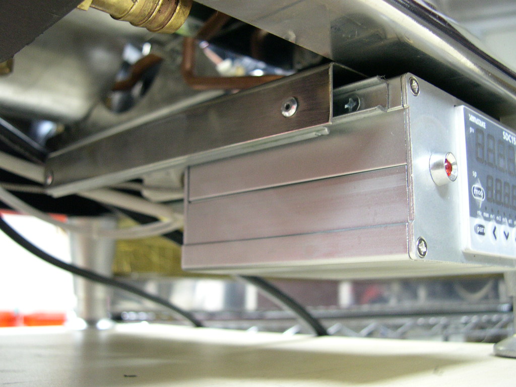
extra $5 and install one now than run the risk of a failed SSR later on. The alumiunium box that I found in an
electronics shop in Kowloon is watertight but I just couldn't mount the sliding runners onto it without it looking a right
old mess. So I made up a stainless steel box for it - a box for the box!
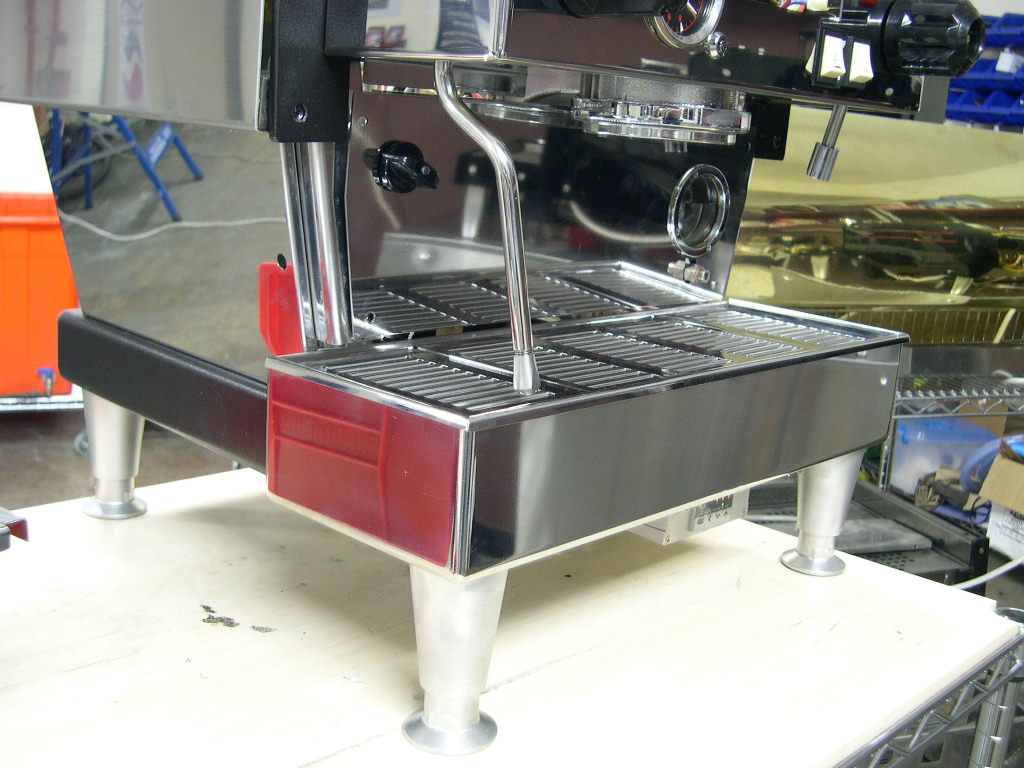
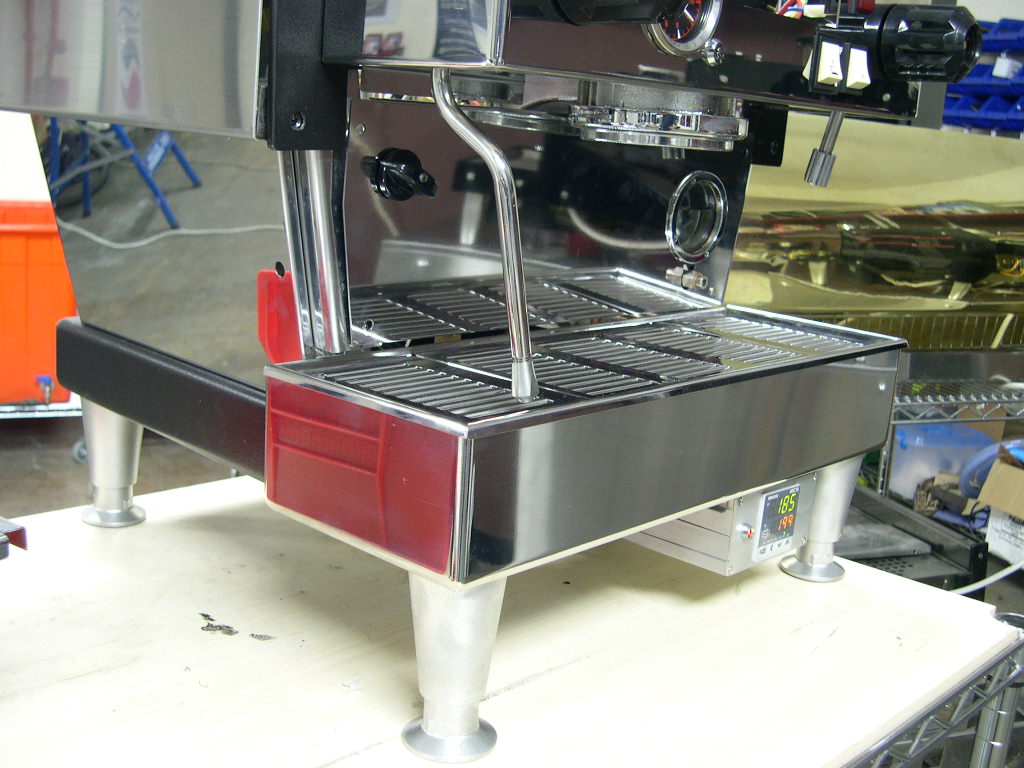
The controller slides effortlessly along on these great ball bearing runners (think a keyboard pull out drawer on a
PC desk) and it travels no more than about 10cm back and forth. In the storage position the unit is locked in place
with one of those spring loaded magnetic latches. Push it to unlock or lock.
will say yes, but please ask first!
Email me here.